• Please review our updated Terms and Rules here

Serial interface for my model 4

Paradroyd

Member
Joined
Aug 12, 2017
Messages
24
Location
Midwest USA
I use my TRS-80 model 4 for BBSing quite a bit. I've been using the Ethernet and tcp/ip stack with the included telnet app that came with the M3SE, which works pretty well, but it's a bit limited in that some BBSs don't like the telnet protocol. As far as I can tell, the telnet that came with the M3SE can't do raw tcp, so i have to do things like hopping through intermediate servers (usually a Decserver and/or Raspberry Pi) to strip telnet out of the mix. This is a bit of a hassle. Plus I'd like to use some of the dedicated terminal programs that only talk to a real serial port (I'm assuming I can't re-direct serial to tcp ports from LS-DOS). I also have a HiRes graphix board, so I'd like to be able to use ANSIterm, which seems to be strictly serial.

My model 4 is a non-gate array model 26-1067, which didn't ship with a serial port or floppy controller, and originally had only 16K (it's since been expanded to 64k).

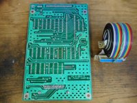
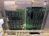
After watching Ebay for a while, I found and bought a serial interface. It looks a bit rough, but it also looks very serviceable. If it doesn't work day one, I think I can probably fix it. I'm including pictures of it in this post.

I haven't been able to find exactly how the card gets mounted to the main board. I have a general idea, just not the specifics. Besides the physical mounting of it, it looks like it's supposed to attach electrically to the top of the main board with some kind of semi-rigid ribbon cable. It looks like 20 conductors. I don't think that that was included with the card, so I'll have to find one somewhere, or rig something up. Any info on what this cable is, where I can get one, or what I can use instead would be helpful. also, any tips on the physical mounting of the serial board (it may be completely obvious, I'll have a better when I actually get the serial card. Looks like I should have it in a day or two).

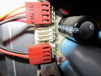
I'll have to tie into one of the power supply connectors too to power the thing. Looks like a standard cable with a couple of 4 pin connectors for that.

Thanks for any info in advance.
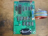
TRS-80-serial_top.jpg
TRS-80-serial_bottom.jpg
 
The cable you're after is indeed a flat ribbon cable. There are no connectors on the end. The cables are annoyingly fragile.

I have a bag of them somewhere and if I could find them, I'd get you a picture of what they look like.

Shoot a PM to Jay Newirth and he can probably help you out. He's a retailer for TRS-80 parts and systems. Jay is the one I bought replacement cables from.

-Kevin
 
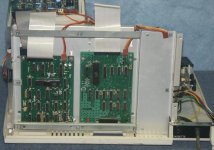
I found a picture online that shows both the location of the serial board as well as the cable. This is a view from the rear of the machine, with the CPU board removed. The serial board is on the right and the floppy controller is on the left.

-Kevin
 
I found a picture online that shows both the location of the serial board as well as the cable. This is a view from the rear of the machine, with the CPU board removed. The serial board is on the right and the floppy controller is on the left.

-Kevin

Thanks, but did you post a picture or link with that message? i'm not seeing anything attached or any hyperlinks.
 
I found a picture online that shows both the location of the serial board as well as the cable. This is a view from the rear of the machine, with the CPU board removed. The serial board is on the right and the floppy controller is on the left.

-Kevin

Ok..after some searching, I think I may have found the picture you were talking about, or one that's pretty much the same...
m4fdcser.jpg

This helps.
 
You need to remove the cover shield on the back of the computer that covers the motherboard
Then you need to remove all connectors from the motherboard and remove it
The FDD and RS232 daughter cards are installed on the back panel (FDD on left and RS232 on right)

The connection cables are very hard to find and I have quite a few sets of them ..... YOU NEED TO BE VERY CAREFUL INSERTING AND BENDING THEM. WITH CARE you will have no problems.
The photo posted shows the (2) white flex cables that you need. I sell them in pairs

NOTE: THE MODEL 4 should have the 2 connectors already inside the machine to attach these (2) cards --- you shouldn't have to "build" any connector. I also sell RS232 cards if the one you get fails.

PS Thanks TROJ for referencing me in this post !!!!
 
Last edited:
Ok..after some searching, I think I may have found the picture you were talking about, or one that's pretty much the same...

Doh! Yes, you found the picture I forgot to include the link to.

Sorry about that.

-Kevin
 
Just be careful with the power cord to the RS232 board - it's wired differently to the motherboard power connector.

If your computer is, as you say, a 26-1067 then it might only have the 35W PSU so there will be a free connector for the RS232 power.

For future reference, when you buy these parts from TRS-80 specialists (like me) they come with the white interconnect cable and, if needed, the power cable.

Here are a couple sets of pictures I've taken of the insides of the model 4 when I've had it apart...

This first set is mostly right after I got it, then after installing the M3SE.

This second set if from another time I took it apart when something had gotten loose and I lost video. (it was just a loose connector.) That set shows the Graphix board installed.

These sets show everything that's in there in great detail. When I'm about to take something apart that I'm not familiar with, I take a ridiculous amount of pictures so that I can get the right things back in the right places. It has saved me many times.

Looking back on these it does look like there are already extra power connector cables in there down by the power supply.
 
You need to remove the cover shield on the back of the computer that covers the motherboard
Then you need to remove all connectors from the motherboard and remove it
The FDD and RS232 daughter cards are installed on the back panel (FDD on left and RS232 on right)

The connection cables are very hard to find and I have quite a few sets of them ..... YOU NEED TO BE VERY CAREFUL INSERTING AND BENDING THEM. WITH CARE you will have no problems.
The photo posted shows the (2) white flex cables that you need. I sell them in pairs

NOTE: THE MODEL 4 should have the 2 connectors already inside the machine to attach these (2) cards --- you shouldn't have to "build" any connector. I also sell RS232 cards if the one you get fails.

PS Thanks TROJ for referencing me in this post !!!!

I've since found out, after looking back through pictures of the inside of the machine, that the power connectors are in there. (See the photo sets that I attached to my reply to Ian.) I'm going to drive by Gateway Electronics this weekend (where I originally got the model 4) on the off chance that they have some of these white flex cables. I never know what they're going to have on any given day. It's likely that they won't have them, but it would save time if they do. If not, of it's OK, I'll PM you to arrange buying a set from you.

Thanks for the info!
 
One more thing...

One more thing...

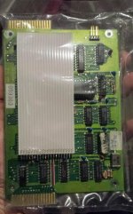
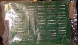
I remembered yesterday that a while back, I had ran across someone selling TRS-80 floppy controllers really cheaply. I bought what looks like a new-in-the-bag a floppy controller for a model 3/4. At the time, I had no idea if it was compatible with my model 4 or how to install it, and I since I had a M3SE coming, I didn't think I would have a use for it any time soon. so I shelved it long enough to forget about it. I remembered it when I started looking at those flex cables, because this controller has one attached, though in this case the interface card side of it is soldered on.

The component layout looks slightly different on this card than on some other floppy controllers I've seen. One obvious thing is that crystal in the lower-right of the card. There are other's I haven't seen that on..at least not in that location. There's a hand-written sticker on the card near the crystal that says, "tested 3-18-88".

It looks like it should be compatible. I'm thinking I might as well try to add it to the model 4 while I have the main board out and everything is accessible.

Any thoughts?

20180808_223632.jpg
20180808_223643.jpg
 
You can always install the board and not plug it into the motherboard (put some insulation tape over the connector) so that if/when in the future you want to mess around with the FDC you can just plug in the white cable and not do the whole motherboard remove/re-install malarkey :)
 
You can always install the board and not plug it into the motherboard (put some insulation tape over the connector) so that if/when in the future you want to mess around with the FDC you can just plug in the white cable and not do the whole motherboard remove/re-install malarkey :)

That's a really good idea. I wasn't really wild about plugging in multiple new interface cards at once. Generally not a good idea, especially when I don't know the full history of them. I don't have a floppy drive or floppy emulator yet anyway.

Thanks!
 
I have just about every part that made up a Model 4 computer --- so if you need anything drop me a PM.

Well, I got the main board out and interface cards physically mounted with no problem, but I wasn't able to connect them electrically, because contrary to what I thought earlier, there don't seem to be any unused power supply cables in there. I did get the interface side of the flex cable inserted with no problem, but I didn't attach the main board side of the flex cables because I didn't think it would be a good idea to hook those up with no power supply leads going to the interface cards (I want to be able to use the machine in the interim).

IMG_0021.jpg

The weird thing is, I only see one unused connector on the power supply, SK3, yet both the FDC and the Serial have open power connectors. Unless there's a (missing) cable that splits SK3 to both controllers, I must be missing something. I'm really only concerned with the serial power at the moment anyway though.

IMG_0040.jpg
IMG_0042.jpg

Looks like I might have to obtain another cable, at least.

For now, the cards are mounted and the model 4 is back together and working fine.
IMG_0050.jpg
IMG_0053.jpg
 
Yes I eluded to that in post #8, diskless M4s will only have a single 35W PSU which is there to power the motherboard, CRT and RS232. If you want to upgrade to disk drives a 2nd PSU is mounted on the disk drive tower (same as the Model III) which powers the two disk drives and FDC.

NOTES:

Be careful when making or buying the power cable for the RS232, it looks similar to the motherboard power cable but is wired differently.

It might be possible to rig up a Y-cable to power the FDC (it doesn't use much power) from the 35W PSU, but there is definately not enough power in the 35W PSU to power motherboard, RS232, CRT, FDC and 2 FDDs.

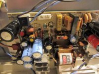
I see your PSU has that ancient Rifa mains filter cap just waiting to explode. Replace it a.s.a.p since your computer is open.

Hope this helps,

Ian.
 
Yes I eluded to that in post #8, diskless M4s will only have a single 35W PSU which is there to power the motherboard, CRT and RS232. If you want to upgrade to disk drives a 2nd PSU is mounted on the disk drive tower (same as the Model III) which powers the two disk drives and FDC.

Ah.. then makes sense then why there's only one (SK3).

NOTES:

Be careful when making or buying the power cable for the RS232, it looks similar to the motherboard power cable but is wired differently.

The connectors on the cable look really simple and common. I don't suppose that the pinouts on that cable are documented clearly anywhere? Seems like it would be simple to make, but without documentation, simple to make wrong too. It looks like the pinouts on the the supply end are clearly labeled (-12, another -12, common, and +5), but there's nothing labeled on the interface end. Even if I buy a pre-made thing I'd like to verify proper configuration before powering it back on.

It might be possible to rig up a Y-cable to power the FDC (it doesn't use much power) from the 35W PSU, but there is definately not enough power in the 35W PSU to power motherboard, RS232, CRT, FDC and 2 FDDs.

The floppy controller was an afterthought. I don't want to stress the supply, so I'll just leave the FDC disconnected for now. I have a M3SE anyway, so I don't need the floppies for transferring things or storage.

I see your PSU has that ancient Rifa mains filter cap just waiting to explode. Replace it a.s.a.p since your computer is open.

Hope this helps,

Ian.

Thanks, it does help! So is there just the one big filter cap I need to replace, or do you think I need to replace all of the electrolytics there?

Thanks again!
 
So is there just the one big filter cap I need to replace, or do you think I need to replace all of the electrolytics there?

Ok..Nix that question. After some research I've figured out the the cap you're talking about isn't one of the big electrolytics at all. It's that weird, rectangular one that I didn't even realize was a cap. That explains why I kept looking for "Rifa" on the cans and couldn't find it.
 
Why not just put an upgraded power supply in .... take out the 35 watt one

If you intend to add floppy drives you'll need to do this anyway

I have power supplies (all power supplies I have are RECAPPED and tested). I have the cable harnesses you will need and I have tons of floppy drives just waiting for a new home.
 
Back
Top