| VCF West | Aug 01 - 02 2025, | CHM, Mountain View, CA |
| VCF Midwest | Sep 13 - 14 2025, | Schaumburg, IL |
| VCF Montreal | Jan 24 - 25, 2026, | RMC Saint Jean, Montreal, Canada |
| VCF SoCal | Feb 14 - 15, 2026, | Hotel Fera, Orange CA |
| VCF Southwest | May 29 - 31, 2026, | Westin Dallas Fort Worth Airport |
| VCF Southeast | June, 2026 | Atlanta, GA |
-
Please review our updated Terms and Rules here
You are using an out of date browser. It may not display this or other websites correctly.
You should upgrade or use an alternative browser.
You should upgrade or use an alternative browser.
SFD-1001 not formatting
- Thread starter Digitalman
- Start date
Digitalman
Experienced Member
- Joined
- Sep 12, 2018
- Messages
- 75
Aha! Your rails are binding. Clean and lube them. Hopefully this simple.")
You think? I tried that before. I'll do a bit more, any particular areas I should target?
I also tried adjusting the speed and then I started to get Format Speed Error. I've since moved it back
You think? I tried that before. I'll do a bit more, any particular areas I should target?
I also tried adjusting the speed and then I started to get Format Speed Error. I've since moved it back
Well on second thought it shouldn't be. Even if the heads were at track two, formatting for 78, verify would read 78. So maybe the head is skewing at that cylinder, the wire is breaking, or you just have disks that don't work at that cylinder. Maybe the alignment is too far toward the spindle and track 78 is outside the recordable area of the disk.
Digitalman
Experienced Member
- Joined
- Sep 12, 2018
- Messages
- 75
Just a thought. But could it be that the head is only reading on one side and the other side is failing?
I thought I read somewhere you could have these drives in a single sided mode some how.
I thought I read somewhere you could have these drives in a single sided mode some how.
So this little program produces the following output.
20 READ ERROR 78 1
first track of side 1 (the top side). I would expect it would first format the bottom side then go back to side 1, at least the 1571 does this, but maybe the old drives would format bottom, top sides then seek to the next track. This error is compatible with bad media, but if it always fails on tracks > 77 (side 1) then it's likely the top head making slightly bad contact with the media surface. I would test for coils continuity on the top head first, then try to slightly increase the head pressure. It would be good to have a picture of the head mounting (you need to remove the metallic screen) on this mechanic.
Frank
Digitalman
Experienced Member
- Joined
- Sep 12, 2018
- Messages
- 75
I would test for coils continuity on the top head first, then try to slightly increase the head pressure. It would be good to have a picture of the head mounting (you need to remove the metallic screen) on this mechanic.
Frank
Definitely starting to get our of my comfort zone. How would I go about "test for coils continuity"? I have a volt meter but would not know where to start. thanks!
Last edited:
Definitely starting to get our of my comfort zone. How would I go about "test for coils continuity"? I have a volt meter but would not know where to start. thanks!
According to the schematic I've found on zimmers:
Locate U10B and U11B, DA1 or DA3 and DA2 or DA4 or R1 and R2, obtain an ohmeter, then:
head 0: measure resistance from pin 6 of U10B to pin 13 of U11B, to pin 3 of either DA1 or DA3 and to pin 3 of either DA2 or DA4. If DAx are not easily accessible, measure to each end of R2.
head 1: measure resistance from pin 5 of U10B to pin 12 of U11B, to pin 1 of either DA1 or DA3 and to pin 1 of either DA2 or DA4. If DAx are not easily accessible, measure to each end of R1
Report these readings, they should be 3 readings on each head, common point is always on U10B.
Frank
Digitalman
Experienced Member
- Joined
- Sep 12, 2018
- Messages
- 75
When taking the readings is the unit powered on and idle?
When taking the readings is the unit powered on and idle?
Unit powered OFF!
I assumed it was understood: voltage/current readings assume the unit is powered on, resistance/continuity checks assume the unit is powered off.
Frank
Digitalman
Experienced Member
- Joined
- Sep 12, 2018
- Messages
- 75
Never assume anything with me! My electronics skills are beginner at best, now I know. I'll report back when I've had a chance to do this.
Thanks!!
My electronics skills are beginner at best, now I know. I'll report back when I've had a chance to do this.Thanks!!
Digitalman
Experienced Member
- Joined
- Sep 12, 2018
- Messages
- 75
According to the schematic I've found on zimmers:
Locate U10B and U11B, DA1 or DA3 and DA2 or DA4 or R1 and R2, obtain an ohmeter, then:
head 0: measure resistance from pin 6 of U10B to pin 13 of U11B, to pin 3 of either DA1 or DA3 and to pin 3 of either DA2 or DA4. If DAx are not easily accessible, measure to each end of R2.
head 1: measure resistance from pin 5 of U10B to pin 12 of U11B, to pin 1 of either DA1 or DA3 and to pin 1 of either DA2 or DA4. If DAx are not easily accessible, measure to each end of R1
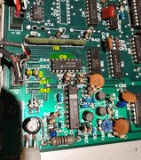
Ok so I may need some more guidance here. After reviewing the schematics and analysing the board I believe I have found the area that needs to be checked. But still not sure what I am doing I can't seem to figure out the pin orientation.
I ran out of time but here is where I am at:
- I was able to get readings on certain PINs from 10B to R1 and R2
- However I would only get a reading for a second or two. is that normal?
- Without flipping the board over I can't get a contact to anything on DA1 or DA2 or 11B
- My multi-meter was set to 200 ohm scale is that correct?
Here is a pic of the area.
-Here are some images of the drive heads as well.
https://postimg.cc/gallery/2s8aa6iku/
Last edited:
Ok so I may need some more guidance here. After reviewing the schematics and analysing the board I believe I have found the area that needs to be checked. But still not sure what I am doing I can't seem to figure out the pin orientation.
I ran out of time but here is where I am at:
- I was able to get readings on certain PINs from 10B to R1 and R2
- However I would only get a reading for a second or two. is that normal?
- Without flipping the board over I can't get a contact to anything on DA1 or DA2 or 11B
- My multi-meter was set to 200 ohm scale is that correct?
-
Multimeter set to 200 ohm scale is ok.
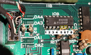
IC pins are counted anti-clockwise starting from PIN 1 which is the first at the left side of the notch, looking from above the chip. Sometimes PIN 1 is idicated with a dot.
So pins on 10B should be easily identified, now, and also R1 and R2 appear to be reachable easily, so forget about DAx. The two pins of 11B that need to be probed can be
substituted by two wires on the black connector near R1,R2 which is the magnetic heads connector. I'm just not sure about the right colors of the wires there.
So if you could just try to take the four readings from 10B and R1,R2, until I check again the schematic and try to understand on what pins of the connector live the two erase coils ends.
Frank
Since you have access to the top head contacts, you could try measuring resistance on these wire combinations (after the results, I can probably give better suggestions):
white-red, white-green, white-yellow, black-red.
Frank
white-red, white-green, white-yellow, black-red.
Frank
Digitalman
Experienced Member
- Joined
- Sep 12, 2018
- Messages
- 75
Ok thanks, I'll get these readings in s few hours. Just so I am clear, this is how I am reading the PINs
Last edited:
Digitalman
Experienced Member
- Joined
- Sep 12, 2018
- Messages
- 75
Ok, looking at the photo and the schematic:
green should be the erase coils,
white should be common connection.
So basicly for each head, you should have 10-16 ohms between white and any other color excluding black.
Frank
So assuming I have done this right, here is what I got.
10B Pin 5 to R1 - 18.7 and 18.5
10B Pin 6 to R2 - 18.1 and 19.2
On the drive head - White (middle) to:
Green: 3.5
Red: 17.5
Yellow - no reading - it shows something on the meter but only for half a second
Black: 16.8 - I know you said excluding, but I took it anyway.
Thoughts?
ok maybe on that head the yellow is a screen, and black is part of the R/W coils.
The readings on U10B to R1,R2 confirm that both R/W coils on both heads are ok.
White to green at 3.5 ohms is way too low however (I'm not saying it's bad, but I need more tests). You should take the measure on the other head, right at the connector (it is next to R1 and R2) or find a way to access U11B pins 12 and 13.
On the connector you should measure between white and green on both rows.
Frank