shank
Experienced Member
Hi everyone... I worked on quite a few of these systems back in the day and taught some classes covering them too. Here are a few notes off the top of my head:
1. Do a complete visual including looking at the card cage connectors, Molex and such. The card cage connectors take a lot of abuse and sometimes the contacts spread causing intermittents. This can drive you crazy. Since these are very old now, I'd also look for broken solder connections on the back of the cage where the connectors are soldered on, or real bugs nesting in there. If your machine came with the metal/plastic brace that holds the cards in straight, you should probably use it.
2. They call it a 5 volt rail for a reason. Check your voltages at the far end of the cage and use a scope. A DVM will give you a volt reading, but it won't show you the ripple. I saw new Astec supplies be spot on with the 5 volts but they rippled like crazy. These machines don't like ripple on the 5 volt line. Check your other voltages too, and make sure they're in spec. I remember +/- 10%, but I'd be happier with 5%.
3. Depending on the type and number of cards you're running, if your 5V is ripple free but low at the end of the cage, you may need to carefully tack some bus wire along the 5 volt rail on the cage to reduce the voltage drop. plus and minus 12 volts are not such a big deal, but be sure and check them too and that they don't ripple and meet spec.
4. Notes and Jumpers is your friend. Grab a copy and read the section on your machine before you begin work. Make sure the jumpers are correct and check your card order and mods -- this is called out in N&J. This was a problem when the systems were new, and I expect it's only worse now. Not all jumpers have metal in them.... And, they don't work so well without it. This should be part of your visual inspection.
4a. Find the relevant Technical Bulletins for your machine and read them, too. Some cards will work even with mods done incorrectly; but they won't work very well. Some won't work at all. Check the mods out and look for correct placement, solder splashes, or shorting kynar wire mods. Make this part of your initial visual inspection. Note: Sometimes the way we did the same mod in the field and mods in the factory were different. Why? We wrote the field mods to be easy to do in a shop--or at a customer's home or business when we did on-site. Generally, the difference was in the gates we picked. The mods did the same thing. This is rare, but it's good to be aware of.
5. Ribbon cables and their connectors go bad. New ones would just stop working because of a manufacturing defect, or they'd be intermittent from heavy handed pushing and pulling. Plugging/unplugging can cause problems and the card edge type suffer the same spread problem as the card cage connectors. Spares are the fastest way to eliminate cables as being problems, if you have the extras.
6. Check the voltages at the drive/s.. I don't know how much value the drives are these days with media problems, but we saw some voltage problems there too. I probably don't have to mention cleaning the heads. I'm not sure how one would align them now without alignment media... With good media, I can align the Shugarts and TPIs by sound and get pretty close. But, I have to hear it boot and that eliminates the CDC drives. Well... I could a million years ago, no telling if I could do it now.
7. If you have to work on the boards, you'll need a scope. Minimium is a dual channel 35 MHz unit with x10 probes. Agilent sells a pretty nifty digital scope product that might work well, but I haven't used it.
8. Diagnostics... If they're available and you have them, use 'em. Mem-II found a lot of problems... And not just memory since it exercise address decoders and a lot of other stuff. Using it with a scope can be a good combination.
This is all stuff you probably know already--nothing magical here, just common sense. I talked to lots of really fine technicians and even they would get in a hurry and skip something simple and end up taking hours troubleshooting what came down to a misplaced jumper or power supply problem.
If you know some Z80/68000 machine code and how to use debug--and your machine will boot, and you have an idea of where your problem is... lot of ifs.. you can use debug to enter short programs to exercise specific parts of the machine over and over in a loop.. say port decoding or like that. you can use your scope to look for that activity, tracing through the same way you might do by injecting a signal into an audio circuit in an amp. This works better in less complex machines (particularly handy in the Model I), but I used the technique a few times on balky 68000 cards since I could bang on them sometimes from the Z80 side. It's an option if you're really into it.
A couple of other common gotchas were that the secondary 35W power supplies in the 6000HD and 16B+ were almost always low both on +5 and +12V (and the internal HDs did not like that very much). And, if you’re working on a 12/16B/6000 with the case off and laid to the side, beware the AC running through the power switch on the left side of the bottom chassis. (Which it does even if you have the switch off but the AC plugged in and you lay a thumb across it when the rest of you is grounded). Even if you don’t get a full ground loop, 120V through your thumb into your elbow and back isn’t a good feeling (I speak from experience.)
Lastly... beware the video. It probably won't kill you unless you grab the anode directly, but what it will do if you get across something is to make you hurt yourself by slicing your hand open as you yank it uncontrollably out of the machine--yep, saw that happen. Take your rings off when working on these old guys so you don't short something or contact HV.
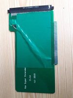
Not video, but be careful using extender cards so they don't short something out that's working, or make something worse that's not. They had a habit of falling out of the card cage at the worst possible moments. I used magazines to keep the cards from touching when I had a board up on an extender unbalanced with a couple of probes attached. Hey.. they were handy...


