• Please review our updated Terms and Rules here

Sony Watchman FD-10A repair.

CompaqSniffer

Experienced Member
Joined
Oct 8, 2024
Messages
119
Location
Charleston SC
Hello, I have a Sony watchman FD-10A I recently got from an antique store and composite modded. Despite performing a pretty decent composite mod, and completely repairing the ribbon cable I ripped for the neck board, I still can't do one thing...

WHY IS THERE NO VERTICAL ADJUSTMENT!!!!!??????

They had the guts to put in the vertical stretch, but there's no vertical adjustment. I can't move the entire image up!!! I've tried every POT on this thing, and nothing is working. I've tried replacing suspicious CAPS and nothing is working. I'm tempted to just start pulling every cap off the board. The only thing stopping me is that I don't have any replacement caps on hand. Am I missing something? Is something broken? Is there something wrong with my PI? I've hooked up my PI to two external monitors and it displays fine, so maybe it's not the PI. I've looked at the schematic, but the schematic I have is for the FD-10E, which is slightly different than the 10A. There's no "vertical hold" (I think that's what it's called) on the schematic for the 10E. Does anyone have any experience with these watchmans? I could use a little help before I break it by accident. I'm trying to make a pip-boy with an actual CRT if anyone wants to know what my plan is for this thing.

This is before the composite mod:
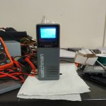
IMG_20250301_220837_HDR.jpg

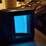
This is after the composite mod (ignore the tilt I was trying to adjust it. This is just a random YouTube video.):
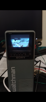
Screenshot_20250302-154136.png
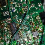
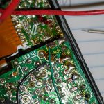
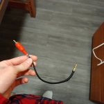
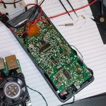
Here's the wiring (I eventually took the tuner chip out, but I left it in at first):
IMG_20250303_210411_HDR.jpg
IMG_20250303_210352_HDR.jpg
IMG_20250303_210404_HDR.jpg

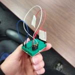
Here's a voltage regulator circuit my professor helped me make so I can power this thing on 6v from the 12v rail of a PC power supply:
IMG_20250303_204940_HDR.jpg

Finished mod:
IMG_20250307_010115_HDR.jpg
IMG_20250307_010143_HDR.jpg

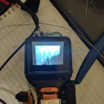
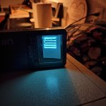
Current state:
IMG_20250309_213027_HDR.jpg

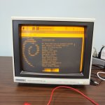
Bonus image of me testing my composite modded raspberry pi-5 on a known working monitor:
IMG_20250307_111314_HDR.jpg

I plan on reinstalling Arch once I get everything in order. I accidentally deleted my partition on my SD card trying to hack my modded switch.
 
What is your input voltage while under load? If I recall these need about 175MA or so.
The picture shrinks quite a bit when the voltage drops.

I have the exact same model and mine is full deflection on the whole screen. I would imagine there's some power regulation circuit to adjust for battery drop and it's the issue. Most of the one's I've seen with vertical issues have been no deflection, or heavy foldover at the top of the screen. Your vertical linearity looks really good. The height looks a bit tall. Overall I doubt the vertical is the issue. What I'm seeing is a weak deflection on both the vertical and horizontal (unless the video being diplayed isn't full screen).

I'd check the obvious stuff (caps) in the power circuit and see if there's anything off.
6.5V under load, it draws about 200 mA. My problem is that it doesn't reach the top of the phosphor, and I can't adjust the vertical position. I only get fold over at certain resolutions. I have been adjusting the horizontal hold and stretch, but the horizontal stretch also stretches the vertical in both directions. There's no vertical hold adjustment from what I'm seeing, and I can't get it to reach the top of the screen without it cutting off the picture at the bottom. I haven't adjusted the horizontal stretch on that picture because that's when I first plugged it in. The current state image is the most of the image I can get on the screen without it cutting off too much.

What caps control the power circuit?
Also what caps are suspect in vertical deflection?
Thanks for your help.
 
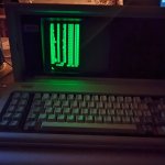
I tested it with my Compaq just to see if the RPI was the problem and it wasn't. It doesn't reach the top plugged into my Compaq either:
IMG_20250313_203953.jpgIMG_20250313_204047.jpg
IMG_20250313_204147.jpgIMG_20250313_204215.jpgIMG_20250313_204624.jpg

I have an external TV I tested it with also, it's also pictured above.
 
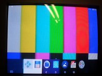
6.5V is plenty good. I run NIMH in mine and I would say it's running at 5.5 to 5.75v. Looking at my screen its also more towards the bottom. When watching TV not noticable and this is the first time I've had a test pattern on it. Mine could do with some adjustment to square up the top corner too.

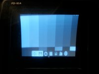
Video source is a MXQ Android TV box with the resolution adusted to just fit the volor screen. it was broadcast through a Blonder Tounge agile modulator on channel 7.

20250301_214952_071952.jpg
Comparing it to a color CRT it's visible that 's also lower than what it should be by the icons at the bottom of the screen. The white line in the color shot is a reflection from the overhead fluorescent lighting hitting the CRT.
20250301_215213_071935.jpg

After looking closely at mine and seeing more pics of yours I don't think there's any problem with your regulator circuits. Maybe they just made them this way. Back in the broadcast analog era there was a rule of thumb to shoot video with 80% of the screen and to avoid putting anything important past this to cover for differences in TV's. The tube sets are even more prone to changes as the warm up.

You could try adjusting the centering rings on the back of the yoke provided there are any. I've never had mine apart so I don't know if they even have them. On a regular inline CRT they will move the picture up and down, and left to right. I think these would be a bit different on one of these tubes with more of a adjustment to how square the picture displayed.
 
6.5V is plenty good. I run NIMH in mine and I would say it's running at 5.5 to 5.75v. Looking at my screen its also more towards the bottom. When watching TV not noticable and this is the first time I've had a test pattern on it. Mine could do with some adjustment to square up the top corner too.

Video source is a MXQ Android TV box with the resolution adusted to just fit the volor screen. it was broadcast through a Blonder Tounge agile modulator on channel 7.

View attachment 1297365
Comparing it to a color CRT it's visible that 's also lower than what it should be by the icons at the bottom of the screen. The white line in the color shot is a reflection from the overhead fluorescent lighting hitting the CRT.
View attachment 1297366

After looking closely at mine and seeing more pics of yours I don't think there's any problem with your regulator circuits. Maybe they just made them this way. Back in the broadcast analog era there was a rule of thumb to shoot video with 80% of the screen and to avoid putting anything important past this to cover for differences in TV's. The tube sets are even more prone to changes as the warm up.

You could try adjusting the centering rings on the back of the yoke provided there are any. I've never had mine apart so I don't know if they even have them. On a regular inline CRT they will move the picture up and down, and left to right. I think these would be a bit different on one of these tubes with more of a adjustment to how square the picture displayed.
I forgot CRTs had centering rings. I'll check, though I'm not sure what I should look for, you might be right that it doesn't have them.
 
Have you tried powering the unit with batteries, or just the regulator you have rigged up? It looks like some sort of linear regulator, which could be a problem. The picture on your CRT has the classic signs of not having enough current.

A linear regulator with such a high power drop isn't going to have a lot of current capability, since it burns the difference between the input and output as heat. And since you don't have a heatsink on it, it's probably getting smoking hot and going into protection. I would suggest using a buck regulator instead, it will give you much more available current.

Another issue could be the correction magnets are out of adjustment, or one of them fell off. If the beam is hitting below the phosphor area, it might need a magnet to pull it back up.
 
I haven't tried batteries yet, I haven't had any on hand. I don't think the regulator isn't supplying enough current, because I told my professor how much it draws(200mA), and he said this regulator should work. It doesn't get hot, it's only mildly warm. I didn't know it had correction magnets, do you know what they look like? I know I can push the beam up to the top by positioning the speaker just right, but other than the speaker, I don't know of any other permanent magnets in the case. I'll try batteries just in case, if power is the issue, then I'll know exactly how to fix it.
 
I've seen all matters of correction magnets, but they're usually square or rectangular and epoxied to the neck or in front of the yoke, depending on how much distortion needs to be corrected.

Home Despot and Lowes sell square magnets that might work. If not, Amazon.
 
The centering rings will be on the back end of the yoke closest to the gun. They have a tab that sicks up so you can rotate them. There should be 2 of them one stacked on top of another.

If there are any magnets they will be small and possibly glued in place. They may rest in plastic channels around the yoke.

Be careful in this area the horizontal deflection is tied to the flyback and then there's likely around 2KV on the second anode. I forget off hand where the connection is on these little picture tubes, but it will be the thickest wire going to the CRT.


Edit I just checked mine and it's using 225 MA
 
Last edited:
The centering rings will be on the back end of the yoke closest to the gun. They have a tab that sicks up so you can rotate them. There should be 2 of them one stacked on top of another.

If there are any magnets they will be small and possibly glued in place. They may rest in plastic channels around the yoke.

Be careful in this area the horizontal deflection is tied to the flyback and then there's likely around 2KV on the second anode. I forget off hand where the connection is on these little picture tubes, but it will be the thickest wire going to the CRT.


Edit I just checked mine and it's using 225 MA

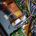
Would these be the centering rings, these gear looking things? I always wondered what they were, it looks like they're glued in place, but I could probably free them up pretty easily.
IMG_20250318_230304_HDR.jpg
Also I forgot to mention I measured the current draw back when I was only powering it off of 5V. I haven't re- measured it yet, but I should definitely do that.
Also does anyone have a picture of the wiring where all of these wires go? I accidentally popped a ground wire off and couldn't figure out where it went too, luckily I managed to figure it out.

Sorry I'm currently a college student and I'm busy with school and I'm also working on plasma screens for the Compaq portable III, so this project is really on the back burner right now. I check up on it a lot, but I don't have time to fully work on it right now.
 
Those are most likely centering rings, but they're a pretty crap design. Most centering rings have tangs on them that you can grab to adjust. Those look like you needed a special tool to turn.

With how much glue is on those things, it's going to be pretty risky to break them loose to adjust them. If you can get away with using a correction magnet on the cone of the tube, I'd honestly try that first. You're a lot less likely to break the tube or damage something else critical by just using correction magnets.
 
Yep those are centering rings. that isn't glue. It's more closer to paint and just pry the rings a bit with a little slot screwdriver and it'll break loose easy. The big screw below it is to keep the yoke clamped in place. This could also be loosened and the yoke turned to square up the picture side to side.
 
I fixed the alignment, however I am severely disappointed with the image quality. It is absolutely atrocious. There's also these vertical bands that are probably caused by bad caps. I probably need to change all of them.
I got it like this by adjusting centering rings.
IMG_20250327_221331.jpg
It looks worse in person, and I can't get it to look like this again, changing the resolution on my raspberry pi gave it some wraparound issues, and now it won't display normally. If also has horrible flickering at lower resolutions.
Anyone got a recommendation for a tiny CRT that has a small back profile? I want to use this to make a pip-boy.
 
Well that looks not bad for NTSC and about what I'd expect. There is a bit of interference that looks like it's also picking up some background oscillation ( the Z shaped pattern on the screen).

I notice the same issues with the TV box too when displaying android's default text. Even the large font is close to unreadable on CRT even on a 20" color TV. A lot of TV's maxed out at around 4mhz so the best you can expect is about 350 to 400 TVL unless you get into broadcast or CCTV grade monitors.

I also question the output quality on some of these modern devices as analog isn't really much of a priority compared to HDMI.

Regarding the flicker, are you sure you didn't end up in PAL mode for Europe tvs on the RPI?

Also if you are displaying a still image on NTSC it will always look flickery or jagged at the edges.

I would imagine you know there's a focus pot on the lower side of the Watchman?
 
Yeah I adjusted the focus to the best place it would go, I'll hook it up to my Compaq to see if it's better, but there's some weird vertical bands that are hard to capture on camera. How do I change modes on my raspi? I didn't even know you can change them, but you might be right, because the video is outputting at 50hz
 
I notice the same issues with the TV box too when displaying android's default text. Even the large font is close to unreadable on CRT even on a 20" color TV. A lot of TV's maxed out at around 4mhz so the best you can expect is about 350 to 400 TVL unless you get into broadcast or CCTV grade monitors.

A lot of that distortion is because the garbage nature of Composite video muxing the chroma and luma signal together. You can get excellent picture quality if you can use SCART, RGB or even S-Video to keep the two signals separate. Or in the case of a B&W CRT, dumping the Chroma signal entirely because it is ignored.

Even the cheap economy CRT displays can get a good picture quality if you can find somewhere on the analog board to inject the signal and bypass the Composite input.

That of course relies on the source device being able to output separate chroma and luma signals, or having the ability to be modified to do that. I've modified several game consoles to output S-Video for my 1992 Sony Trinitron TV. The quality difference is night and day. What used to be a hot mess of blurry text is now near pixel perfect.
 
I've heard about RGB modding CRTs, and seen a video on it I put on for background noise, I actually purchased a cheap orion CRT I might try to RGB mod for my first attempt. It's got a built in VCR on it which I might just gut and put game console guts in. maybe a built-in snes or nes. The only problem is that the TV doesn't work currently, The power comes on but the tube doesn't. I looked at the back to see if the heater glowed, but there was no glow. Gonna require more troubleshooting.

This sony watchman is really my first experience with modding a CRT, and I chose it because it has such an easy composite mod. how would you RGB mod the raspberry pi? because the rpi only has composite out, and hdmi. and how would you go about modding the watchman?

I have a schematic for it from archive.org, but it's not for the FD-10A, it's for the FD-10E. It's similar enough to be somewhat useful for the FD-10A.
 

Attachments

I guess I should say what I'm actually trying to do with this CRT, that way I can get a better idea of how to go about things.
I'm looking to make a game-accurate pip-boy that uses an actual CRT. For anyone who doesn't know, a pip-boy is a wrist mounted computer from the Fallout game series, that takes inventory of your belongings, records your vital signs, plays radio, and measures radiation. I wanted to go with a CRT with this build because I wanted it to be made out of "junk" parts. I went with this sony watchman FD-10A as a impulse buy, seing as I've never seen a CRT that thin before.

Now that I have it displaying a picture, I'm kinda having second thoughts, and I think I want to ask if there are any crts that are better suited to what I'm trying to do.

Out of all the research I've done, I haven't been able to find a CRT that fits the size constraints I want. I want the screen to be no larger than about 4in in length, and the most important part is the back profile of the tube. The tube has to be as long as it is wide, which is somewhat impossible to find looking up videos for the smallest CRTs, and researching small crts in general. most of them have tiny screens, but the necks are incredibly long. The best CRTs I have found are the ones that have electron guns mounted perpendicular to the phosphor, so mostly sony Watchmans. the one CRT that I found that could work that is normal is also a sony watchman, It's model is FD-500. this one is about 4in wide, and looks like it is as long as it is wide. The only problem with the FD-500 is that there's no pictures of it taken apart so I can get a good grasp on what the tube actually looks like.

Does anyone have a better CRT recommendation? Most CRTs of the size I'm looking for are black and white, but it would be a nice bonus if there existed green or amber ones, a color one would also work if there exists color ones that are short enough. I'm really looking for any CRT that matches sizes I'm looking for. So far the flat watchman CRTs are my best bet, but I want to try to avoid having an appendix poking out from the top or bottom, it would be nice if the electron gun were mounted to the side instead.
 
Last edited:
This sony watchman is really my first experience with modding a CRT, and I chose it because it has such an easy composite mod. how would you RGB mod the raspberry pi? because the rpi only has composite out, and hdmi. and how would you go about modding the watchman?

There are RGB boards for the Pi, like this one: https://thepihut.com/products/rgberry-scart-rgb-arcade-hat-for-raspberry-pi

That'd only get you halfway there though, you'd need something to convert the RGB to component video. You could just bodge on a converter chip, like a Sony CXA1145, which can convert RGB to component video with some passive components.
 
Back
Top