Hey there fellas,
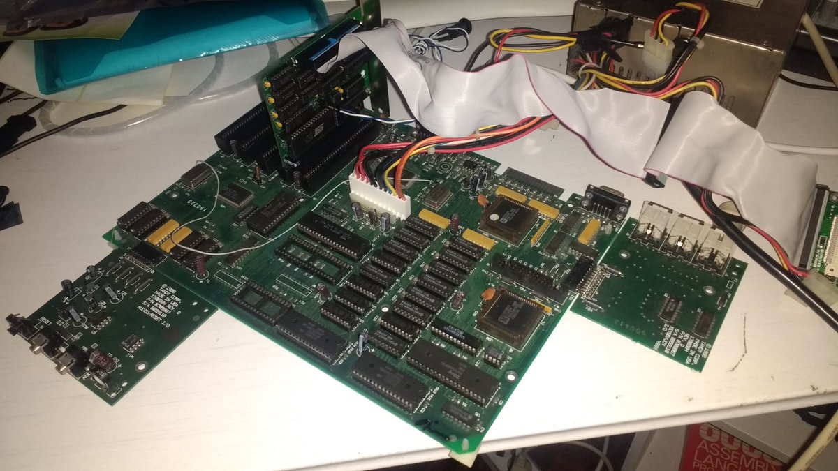
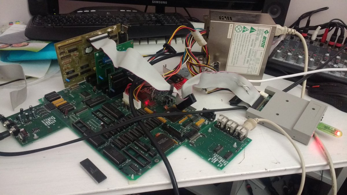
i recently got a loose Tandy 1000 SL motherboard, including both satellite boards. I've always wanted a Tandy 1000 system. The Tandy i'm really after is the TL/3, but these are a little hard to find. Let alone the cost of shipping one from the US to Europe. Canada is even worse...
I've always wanted a Tandy system and i also wanted a 8086/V30 system. Generic 8086 XT boards are extremely hard to find, so i thought i would kill 2 birds with one stone. However an 8MHz V30 is a very small improvement on a 12MHz V20, and since the desired speed for a V30 system for me would be 10MHz i'm wondering if it's easy to replace the crystal on a Tandy 1000 SL.
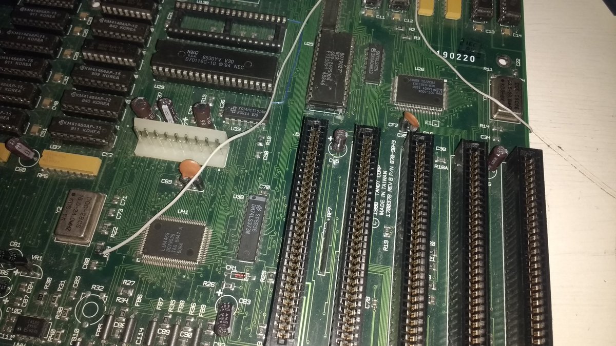
From the pictures i can see the board has 2 crystals, although i can't see the values, but i assume the 2 crystals at least gurantee one is used for the 14.318MHz ISA bus / timer etc... and the other for the CPU.
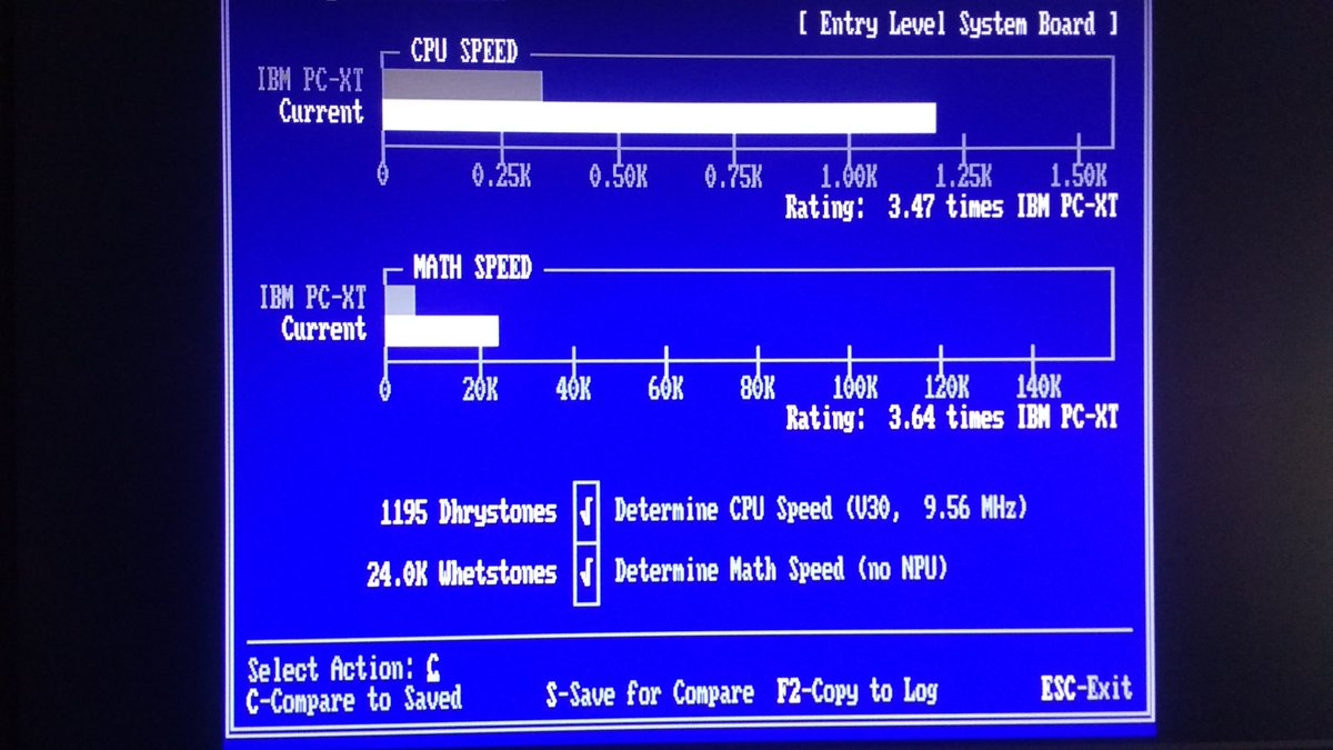
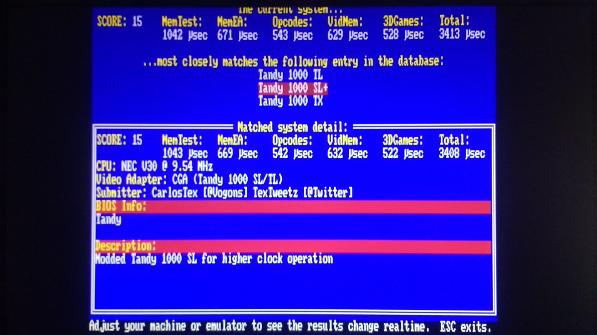
I assume the CPU is using a 24MHz crystal which will give 8MHz divided by 3, so i'm wondering if changing to 30MHz will overclock the CPU to 10MHz without affecting the system to a point of instability. Usually 10MHz is well tolerated.
Has anyone tried to overclock a Tandy 1000 SL? If so, what were the results?
i recently got a loose Tandy 1000 SL motherboard, including both satellite boards. I've always wanted a Tandy 1000 system. The Tandy i'm really after is the TL/3, but these are a little hard to find. Let alone the cost of shipping one from the US to Europe. Canada is even worse...
I've always wanted a Tandy system and i also wanted a 8086/V30 system. Generic 8086 XT boards are extremely hard to find, so i thought i would kill 2 birds with one stone. However an 8MHz V30 is a very small improvement on a 12MHz V20, and since the desired speed for a V30 system for me would be 10MHz i'm wondering if it's easy to replace the crystal on a Tandy 1000 SL.
From the pictures i can see the board has 2 crystals, although i can't see the values, but i assume the 2 crystals at least gurantee one is used for the 14.318MHz ISA bus / timer etc... and the other for the CPU.
I assume the CPU is using a 24MHz crystal which will give 8MHz divided by 3, so i'm wondering if changing to 30MHz will overclock the CPU to 10MHz without affecting the system to a point of instability. Usually 10MHz is well tolerated.
Has anyone tried to overclock a Tandy 1000 SL? If so, what were the results?
")