• Please review our updated Terms and Rules here

Tektronix 4052/4054 Multifunction modules available.

Hi Monty, yeah, it's been a while! :)

Jos is still on to it. I understand he now concluded the DS we've got now aren't fakes, but there appears to be an issue with the GALs. Will keep you posted when we know more.

TBH I've been pretty much absent from my Tek and SGIs lately. Job woes and whatnot...

More soon. Take care!

--Roland
 
Hi Roland, as mentioned in the PM : the issue with my machine was a short in the backplane connector. It is now OK again, both RTC chips and GAL's were OK.
more per PM.

BR Jos
 
I figured out my issue with getting the MFM RS-232 printer interface to work again - my rewiring of my DB-9 connector had only changed one of the two handshake signals, now my MFM RS-232 printer interface works.
Hi all, and I hope it's no faux pas to revive an old topic in this thread. @nikola-wan , I'd love your help :)

I have an MFM and I'd like to use its built-in serial port to send some output to another device. (I don't need input at the moment.) I haven't been able to get this to work, and Jos directed me to this thread. My simple goal is for a 4054A with the MFM to send data over serial to a Linux machine with a serial port. I'm flexible about handshaking so far as it's something Linux likes (so as Monty notes, RTS/CTS is more useful than DTR/DSR), although for my application NO handshake is fine and maybe even better.

It looks like the information I need is in this thread, but it also looks like there are several things tried and maybe determined not to be necessary. I have to admit that I'm having a bit of a hard time following along: it looks like there may be board modifications to the MFM, but perhaps you can accomplish some of the changes with a specially-made serial cable? So:

1. Is it possible to get a step-by-step list of things to do to get an MFM to be able to send data over serial to a Linux box? A list of steps like
"cut trace X",
"add a jumper between pin Y of IC Z and DE-9 pin W",
"make a cable where pin X on the MFM end connects to pin Y on the Linux box end"
and so on? This might seem a lot of work, but I'm willing to help out if I can; maybe I can refine a sketch from you that refers to existing posts?

2. Once these steps are complete, what's the easiest way to test basic operation? For example, with the MFM installed, I tried PRINT @41:"Hello", but this yielded an Error 67 on the 4054A if I recall correctly. I believe the MFM was in the correct slot for this address, but no serial cable was plugged into it, which might matter. (NB: For testing instructions, I don't need any help with the Linux box side of things.)

I try not to need all of the handholding I'm asking for in (1) above, but in my case I've got a bit of a disadvantage, as I have pretty good reason to think my MFM could be malfunctioning. (50% odds, I think.) The double-task of devising a set of "normal" setup steps AND troubleshooting a broken module seems pretty tricky, so being certain that I was doing the right thing for (1) and (2) above would be an immense help in dealing with any problems. Thanks for any assistance!
 
Hi Tom!

I assume you have the RS-232 Printer I/F ROM loaded at the MFM ROM HEX address in my earlier post in this thread?
https://forum.vcfed.org/index.php?threads/tektronix-4052-4054-multifunction-modules-available.76192/post-951075
Jos' MFM decode for the RS-232 hardware requires the RS-232 ROM be loaded in MFM ROM slot 3 as the RS-232 hardware is decoded into ROM Expander slot 53.

You installed the MFM in the right slot - slot 2? The slot 2 in the two-slot backpack decodes a ROM Expander into slots 51 to 58.

If you have the 4-slot backpack - I think you will need to insert the MFM into the second slot (which decodes a ROM Expander into slots 51 to 58).

The 4054A "CLIST" does not report any new CALLs for the RS-232 Printer Interface because there are no new CALLs - it only works with PRINT LIST, SAVE and TLIST - using the Secondary Address based on which slot the interface is plugged into!

The original RS-232 ROM Pack could be installed into ANY slot - but the BASIC commands PRINT, LIST, SAVE and TLIST(only works on the internal tape drive) will only work with @53: with the MFM RS-232!

Monty
 
Thanks Monty. I think there might be something fishy going on with my MFM.

I've confirmed that the RS-232 ROM is in the third ROM slot: bytes $8000 through $BFFF.
My MFM is fitted in the second slot of a four-slot backpack.

Voltages look suspicious, and I wonder if this is something you could compare with your own MFM (assuming you haven't modded it). Using pin names from the schematic,
Pin 1 (DCD) is at -12V. This seems maybe suspicious? Unless this pin is the same as "RLSD" from the printer interface manual page 2-4?
Pin 2 (RX) is 0V, which seems normal.
Pin 3 (TX) is -12V, which seems normal.
Pin 4 (DTR) is at 0V. This seems suspicious? DTR in the printer interface manual page 2-4 is supposed to be pulled high?

Before I continue, I actually don't care about the MFM serial port right now: all I really want is a way for the 4054A to toggle/twiddle a single I/O line under BASIC program control. The serial port seems like an easy way to try to do this: sending data out the serial port gives me something I can detect. I don't know what other options there might be; I don't have the time to make my own GPIB device, and anyway, the Flash Drive is hogging that port already :) Can anyone think of a way to accomplish this? A lot of the other options besides the serial port seem very complicated. If it helps, you can assume that I'm OK running the computer with the covers off.

Back to the MFM.

Every attempt to print to slot 53 (e.g. PRINT@53:"Hello") results in an I/O failure: message 67 in particular. I get the same if I try to print to any other slot. I'm not sure why this should be. @jdreesen , do you have any idea?

Neither that phenomenon nor the strange voltages on DCD and DTR seem likely to be the fault of the MC6850 --- I swapped in a spare MC6850 that I have. It's possible that IFC1, the 75155 IC for the control lines, is faulty; I have spares but haven't tried swapping one in yet.

Thanks for any help!
 
Hi Tom, did you try your MFM in one of your 4051 computers?

I suggest running my Checksum program on the 4051 or 4054 with MFM in slot 2. The checksum program will indicate which Expansion slot it finds each ROM - including the RS-232 Printer Interface.

In my photo attached - I think the RS-232 Printer Interface ROM is the "Unknown ROM Pack" with 2350 for the first 4KB checksum.
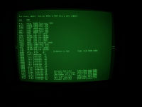
my-4054A_ROM_Checksums.png

RLSD is now called DCD - which is connected to ground in the MFM schematic Rev 0.1 that I'm looking at from Jos' MFM pdf.
That schematic shows the RS232 pin 1 is connected to RTS on the 6850 although the signal name on the schematic is dcd.

You can probably rewire the 75155 buffer input to DCD on the 6850 - but you would need to cut the DCD trace to GND - or lift the UART DCD pin out of the socket and wire to the lifted 75155 pin if that IC is also socketed.

@jdreesen would know if the schematic I'm looking at is the current MFM board schematic.

If you don't care about the 4050 speaker - it is a GPIO that you could use - but it would require an assembly language routine to set or clear it.

Alternatively - you might try using the COM Option 1 interface.
Appendix A-1 has an interesting paragraph on ERROR message 141:

141-I/O Function: Programmers error. Attempt at BASIC I/O with device 40 with incorrect
secondary address. INPUT from 40 is only correct when secondary address=4(OLD),
13(INPUT) and 0(STATUS). Output correct when secondary address=1(SAVE), 12(PRINT),
19(LIST), 30(ON) and 31(OFF).

I tried PRINT@40,30:0, PRINT@40,30:1, PRINT @40,31:0 and PRINT @40,30:1 and got no error!
I wonder if 30 is the secondary address for controlling the COM RLSD signal on pin 8 of the 25 pin connector on the COM Backpack. I searched that manual for mention of 30 or 31 and didn't find any other mention

I also tried PRINT @40,11:0 and got error 138 - which is not listed in Appendix A-1!

The RS-232 Printer Interface manual page 3-2 shows how to control the RLSD signal:
PRINT @41,11:0 to set the RLSD OFF
PRINT @41,11:1 to set the RLSD ON.

I think it might be worth your experimenting with the COM backpack RLSD signal!
 
Last edited:
Thanks for the reply!

Hi Tom, did you try your MFM in one of your 4051 computers?

I didn't think a 4052/4054 MFM could work in a 4051? I haven't tried to use it there and am wary of trying. Can the 4052 MFM work in a 4051? I thought the expansion ports were physically incompatible...

I suggest running my Checksum program on the 4051 or 4054 with MFM in slot 2. The checksum program will indicate which Expansion slot it finds each ROM - including the RS-232 Printer Interface.

I haven't done this, but I will try it if I get desperate. The reason I haven't tried it is because I dumped the MFM ROM myself last night onto a modern laptop and verified that the contents at $8000 through $BFFF are byte-for-byte identical with the ROM data available in this file on your Github repo. This should be an equivalent validation to what the Checksum program can do. But I will give it a try if I am wholly out of answers.

All of the other ROMs in the MFM appear to be working, or at least they show up correctly when I do a CALL "CLIST", so I think any communication between the 4054A and the MFM is working. Judging by the schematic, my impression is that this also validates the the GAL, the data bus buffer, and the bank switch register. The 6850 has also been replaced. The RTC doesn't seem too related; I haven't checked it, but it was working a while ago. There are not too many parts left to go wrong...

RLSD is now called DCD - which is connected to ground in the MFM schematic Rev 0.1 that I'm looking at from Jos' MFM pdf.
That schematic shows the RS232 pin 1 is connected to RTS on the 6850 although the signal name on the schematic is dcd.

You can probably rewire the 75155 buffer input to DCD on the 6850 - but you would need to cut the DCD trace to GND - or lift the UART DCD pin out of the socket and wire to the lifted 75155 pin if that IC is also socketed.

I think I'm looking at the same schematic. Based on the conversation earlier in this thread, it sounds like you've rewired your MFM to support CTS/RTS, or at least to support some kind of successful output to a different device. If that's true, can you tell me what your final configuration was?

@jdreesen would know if the schematic I'm looking at is the current MFM board schematic.

If you don't care about the 4050 speaker - it is a GPIO that you could use - but it would require an assembly language routine to set or clear it.

That's my only other idea. It should be possible to generate a tone with R12 --- the hard part then becomes detecting the tone reliably.

Alternatively - you might try using the COM Option 1 interface.

I do not have Option 1 fitted on the 4054A, unfortunately.

I also tried PRINT @40,11:0 and got error 138 - which is not listed in Appendix A-1!

The RS-232 Printer Interface manual page 3-2 shows how to control the RLSD signal:
PRINT @41,11:0 to set the RLSD OFF
PRINT @41,11:1 to set the RLSD ON.

I think it might be worth your experimenting with the COM backpack RLSD signal!

Thanks for looking this up along with the Option 1-related details. I did try PRINT @43,11:0 and encountered the same error 67 that has been the typical experience so far.

I will try replacing the 75155s now. Very mysterious...
 
I've now replaced the 75155s. Everything is as it was before except now Pin 1 (DCD) rests at a little below +3V. The mystery continues.

The 4050-series reference manual reports error 67 as: "An attempt has been made to execute an illegal I/O operation on an internal peripheral device. Example: DRAW@33:50,50".
 
Last edited:
Well, colour me surprised: I ran the checksum program, and it looks like whatever I have on the MFM doesn't match what you have: https://photos.app.goo.gl/GsYqBZga4tAL4osg7

When I do CALL "CLIST", I see the same listing you see here: https://github.com/mmcgraw74/Tektronix-4051-4052-4054-Program-Files/blob/master/4054_Option30_ROMs/Toms MFM CLIST annotated.jpg
plus an extra line containing the callables from the DRP.

@nikola-wan , do you think you would mind sharing the ROM data from your MFM?
 
I will look into creating a guideline for using the RS232 interface.

However if you are only interested in toggeling a pin there is a wholly different approach possible : take a look at my 4052 RAMpack design, there I control the TTL counters directly from my 4052 machine. You have a RAM pcb, you would only need to stuff the 74LS245 buffer, the GAL and 2 of the counters : voila, 8 TTL output bits under your control !
I provide the 4052 assembler source for the controller rom, there you can see how it is done an how you coulde create another BASIC CALL command to easily use this setup

It would be trivial, although a lot of work, to make a general I/O module, providing an 8-bit input, 8-bit output, and while we are at it, some DAC and ADC's...Not that I really have time for yet another project....Retired people, you know...

[edit] I stopped developing the RAMPACK design after the SD-card solution was offered. I might yet continue the RAMPACK design as the USB-interface has its own merit, and the IEEE interface would remain free.
 
Thanks for the comments! However I think what I just need is to correct my installation of the RS-232 ROM image --- I'm under a bit of time pressure, I have an MFM, and I have a breadboard and a pile of comparators and reed relays to get me where I need to go. As fun as it sounds, I don't think I have time to hack the RAMpack into working --- as you may recall, I don't own this 4054A, and it must return to its owner before too long. If I can just get PRINT@53:"whatever" to work, then I can whip something together and move on. It now looks like all I might need is a proper ROM.

@jdreesen or @nikola-wan , would you be able to share me a copy of the contents of your working MFM ROMs? Or, perhaps you could take a look at mine (attached) and identify a problem with it? Thanks both!
 

Attachments

  • mfmrom.zip
    42 KB · Views: 2
Thanks for the comments! However I think what I just need is to correct my installation of the RS-232 ROM image --- I'm under a bit of time pressure, I have an MFM, and I have a breadboard and a pile of comparators and reed relays to get me where I need to go. As fun as it sounds, I don't think I have time to hack the RAMpack into working --- as you may recall, I don't own this 4054A, and it must return to its owner before too long. If I can just get PRINT@53:"whatever" to work, then I can whip something together and move on. It now looks like all I might need is a proper ROM.

@jdreesen or @nikola-wan , would you be able to share me a copy of the contents of your working MFM ROMs? Or, perhaps you could take a look at mine (attached) and identify a problem with it? Thanks both!
Tom,

You don't have the printer I/F ROM starting at 8000 hex, I see it start at 9000 hex - that is why it isn't detected.
First ROM is at 0000, second at 4000 third at 8000 ...

Here is my MFM image
  • slot 1 (0000h) - Signal Processing #1
  • slot 2 (4000h) - nothing
  • slot 3 (8000h) - Printer I/F
  • slot 4 (C000h) - 741RTC TransEra
  • Slot 5 (10000h) - 750SPU TransEra Super Utilities
  • Slot 6 (14000h) - R12 Enhanced Graphics
  • Slot 7 (18000h) - 764MEM TransEra
  • Slot 8 (1C000h) - Character & Symbol
The first sixteen bytes of the ROMs are typically all FF but could be 00.
The 'ID' of 40 52 starts at offset 10 hex.

Each 4052/4054 ROM pack could contain up to four 4KB 2732 EPROMs, but some of the ROM packs only contain one, two or three 4KB EPROMs.

Hope that helps!
 

Attachments

  • myMFMimage SP1-Printer-741-750-R12-Aux-chr&Symbol.zip
    31.4 KB · Views: 0
Last edited:
Yep, that seems to be the problem. The printer driver software is shifted by 4K.
Other potential pitfall : the 6850 needs to be the 2MHz variant, i.e. 68B50.

If alls fails : a very quick hack to obtain a programmable bit : add a 74ls74, with set and reset coupled to the 68B50. Reading/writing the UART sets/reset the '74.
 
Thanks both, I'd noticed that offset too late last night and had wondered if that was what mattered. For what it's worth, the binary file in @nikola-wan 's GitHub repo,
starts with four kilobytes of 0xFF as well, so if you naively put that ROM data into the third slot on the MFM ROM as I had done, then you get the offset.

I will try to update the ROM soon and let you know what happens.
 
Apologies, that error was coming from my side. I mixed up the script that generates the ROM binaries.
Sorry for the timewaste ...
 
No worries; it all started when I put the MFM into the computer backwards months ago. I thought I'd fried something, but I hadn't: it turns out to have been the ROM issue all along. If I hadn't suspected hardware, I would have worked out the ROM issue much sooner instead of swapping parts. In the end, that's all it was.

Everything now works quite well. It turns out that the 75155 replacements I had done earlier were unnecessary and even detrimental: one of my replacement ICs from eBay was damaged by the time I'd fitted it, hence that strange ~+3V measurement on Pin 1. I put the old ones back and saw -12V as it should be. It wasn't bad to have extra 75155s, though, since I could just use one of them at the other end of the cable to convert Pin 1 back to TTL. By default, the Tek raises Pin 1 to a steady +12V while it sends anything, so I can just send a long, arbitrary string at 300 baud for the Tek to "push a button" for a little while. The final setup was:

Tek -> MFM pin 1 -> 75155 rx channel -> TTL buffer (actually a pair of inverters in a 74LS06, since that's what i had handy) -> reed relay ("the button")
 
@GanjaTron - Did you get your MFM ROM Pack RTC working?

Hi Monty, hi everyone,

hope you're enjoying the waning Easter break. I just wanted to confirm that I finally did get my MFM working -- with Jos' invaluable help. Thanks, Jos!

It turned out that the DS12885 RTC was indeed faulty -- or fake. Whatever. No more silly endless password prompts. Also, I've successfully tested the GAL and PALCE in the MFM; both work fine.

Looking forward to trying out Monty's Enhanced Grafix demo!

Best regards and thanks again,

--Roland
 
Great news Roland!

I made progress on my 4054A display problem today.

I started checking the high voltage power supply Control Grid power components and R263 was open instead of reading 1M. I didn't have a 1M 1/2 Watt carbon composition resistor so I substituted two 1/4 Watt carbon film resistors (I know they have some inductance) a 2.2M and a 1.8M in parallel (which I measured with my DER EE LCR Meter and got 999.1K) and the orange bright spot is gone - and now my CRT BIAS pot can adjust out the dot in the corner of the blinking orange cursor - YIPPEE!!

I'm now running through the 4054 display calibration steps, hopefully my 4054A will be back in full operation after calibration.

--Monty
 
Back
Top