• Please review our updated Terms and Rules here

The case of the mystery capacitor

NHVintage

Member
Joined
Oct 1, 2023
Messages
24
Hi there! I have a friend working on an Apple II, cleaning it up etc, and he's come across a capacitor attached across points on the motherboard in what is clearly a non-factory bodge job, see pic attached. Do any Apple II gurus out there have an idea why this might have been done? some sort of mod? Img_7150.jpgImg_7149.jpg
 
A picture of the top side might help. The identity of the component the capacitor is soldered to would be a good clue.

All the Apple II motherboard pictures I can find show a bunch of ferrite filters there, so more than likely that capacitor is for extra noise filtering on one of the power supply voltages.
 
Unless its a clone or some prototype.. Or a foreign model (non US) I am sure you can remove that cap. ITs across the ground pins of the psu connector
 
As Kelly Gray indicated, the capacitor is tying one of the voltages to ground. This is know as a decoupling. I am not sure which voltage that pin is connected to without probing one of my boards. High frequencies will travel through the capacitor to ground, thus removing them from the voltage line. In addition, the capacitor acts as a short term power source for that voltage line if a drop occurs.

My guess is a previous owner had a power supply that created ripple on that line and the capacitor was added to clean it up. Another scenario is the owner filled most of the slots with cards and the system started acting flaky.

Personally, I would leave it in place. It is on the bottom of the board and appears to be well done. It is not going to hurt anything unless the cap goes bad.

Marvin
 
As Kelly Gray indicated, the capacitor is tying one of the voltages to ground.
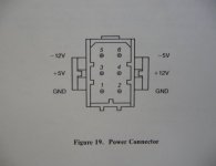
Nope, its connecting both of the ground pins on the psu connector like I mentioned. Not a voltage rail: a2psu.jpg


I would check the voltages while the machine is on (5v, 12v etc.) then remove one leg of the capacitor and check again. IF there is no visible change to votlages, video, or behavior, remove it. It clearly was not installed that way at the factory because of how badly and dangerously they mounted it..
 
Both Kelly Gray and Marvin are correct.

The negative terminal of this electrolytic cap has been soldered to both ground pins of the power connector. The positive terminal of the cap has been soldered to the +5V supply line feeding the expansion connectors. As was pointed out by Marvin its purpose was to provide additional filtering for the +5V supply likely because the original owner noted the system was becoming "flaky" as additional cards were added.

There is no harm in leaving it, however a sleeve of insulation should be put over the exposed wires on both ends of that cap so they do not accidentally contact the traces on the solder side of the board.
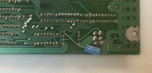
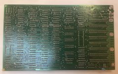
I got out one of my II Plus boards today and confirmed that the cap's positive lead is connected to the +12v rail.
 
Thank you all for that information and apologies for the delayed answer, work and life is perpetually busy it seems. I've passed that on to my friend. A new power supply is being put in (a modern one from the Retro site that makes them) so I believe he'll be removing that capacitor.
 
Back
Top