Hey all, does anyone happen to have a TRS-80 CM-1 Monitor (Model No. 26-5112) that they'd be willing to open up the case on and take a picture of the bottom of the board in for me?
I opened mine up to double check that nothing was obviously wrong before powering it up and I noticed it had that old sealant/silastic the tends to become conductive over time. I checked it with my multimeter and it was indeed conductive for some of it. It had a very high resistance, but I wasn't wanting to risk it causing a problem in the future, so I set about getting it all removed and using some non-corrosive silicone in its place.
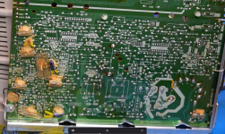
Well, like a dumb-dumb before taking pictures of the board, I removed a resistor that was on the bottom of the board near the flyback transformer and now I'm not 100% sure which two pins the it was soldered to on the bottom of the board. I'm confident in one of them, since looking at the solder it's obviously been reflowed and I think I know the other one, but I'd rather not risk damaging anything. I'm marked the two points where I think it was soldered to. I'm confident in the one on the left, but not the right. The one marked on the right looks like I might have melted it with my soldering iron, but I'm not sure.
Looking closer it might have gone to pin 5 on the flyback. There's a hole in the solder blob that looks like it could have had the leg of the resistor in there and it just didn't heat up enough to flow back in and fill the hole. Pin 5 on the flyback is a ground pin when I check with my multimeter. The point I'm confident about goes directly to pin 6 on the flyback. The arrow on the right goes directly to pin 3 on the flyback.
There is a resistor installed there on the top side of the board at the two points marked in the attached image (the one on the bottom is a 1.8 MOhm and the one on the top side of the board is 330 kOhm).
I've not been able to find any pictures of a CM-1 that's been opened up. The board and tube were manufactured by Mitsubishi. The P/N on the board is 240A15701 (I think it's the former). I think the Mitsubishi model number is G0194V-0. That shows up on both the main board and the neck board.

I opened mine up to double check that nothing was obviously wrong before powering it up and I noticed it had that old sealant/silastic the tends to become conductive over time. I checked it with my multimeter and it was indeed conductive for some of it. It had a very high resistance, but I wasn't wanting to risk it causing a problem in the future, so I set about getting it all removed and using some non-corrosive silicone in its place.
Well, like a dumb-dumb before taking pictures of the board, I removed a resistor that was on the bottom of the board near the flyback transformer and now I'm not 100% sure which two pins the it was soldered to on the bottom of the board. I'm confident in one of them, since looking at the solder it's obviously been reflowed and I think I know the other one, but I'd rather not risk damaging anything. I'm marked the two points where I think it was soldered to. I'm confident in the one on the left, but not the right. The one marked on the right looks like I might have melted it with my soldering iron, but I'm not sure.
Looking closer it might have gone to pin 5 on the flyback. There's a hole in the solder blob that looks like it could have had the leg of the resistor in there and it just didn't heat up enough to flow back in and fill the hole. Pin 5 on the flyback is a ground pin when I check with my multimeter. The point I'm confident about goes directly to pin 6 on the flyback. The arrow on the right goes directly to pin 3 on the flyback.
There is a resistor installed there on the top side of the board at the two points marked in the attached image (the one on the bottom is a 1.8 MOhm and the one on the top side of the board is 330 kOhm).
I've not been able to find any pictures of a CM-1 that's been opened up. The board and tube were manufactured by Mitsubishi. The P/N on the board is 240A15701 (I think it's the former). I think the Mitsubishi model number is G0194V-0. That shows up on both the main board and the neck board.