• Please review our updated Terms and Rules here

TRS-80 model 4 gate array toubleshooting

mykrowyre

Experienced Member
Joined
Jan 28, 2019
Messages
171
Location
Saint Augustine, FL
I have a model 4 gate array I just purchased which had a HXC2001 floppy emulator installed and the floppies removed. I came with a pile of disk drives.

It tries to boot from SD card but I didn't have a valid config file so it complains. I removed the floppy emulator so I could re-install the original floppy drives.

I have a pile of 6 original floppy drives, all single sided, none have terminating resistors.

The original floppy cable is the one with pins removed to activate only 10 and 12 for drive 0 and 1 so terminating resistors are not required.

Of the 6 drives, one of them will give a "Diskette?" prompt when installed alone at the end of the cable.

If I insert a disk and reset, it will boot but the display will suddenly tear as if it's lost sync, but I can see activity as the machine boots and text is printed. I see more torn lines appearing as I hit enter.

For the other floppy drives, none of them give me a "Diskette?" prompt. Instead I get a black screen. They will still boot on reset resulting in the same screen tearing.

If I power on holding the break key, I get a cassette basic prompt even if I get the black screen initially.

I am booting from a CP/M disk it's all I have.

So my question is: Is CP/M trying to boot in 80 col mode which is causing the monitor to lose sync due to another issue?

What would prevent the machine from displaying "Diskette?" when I install any of the other 5 disk drives?

At first I thought the drives had bad caps and were pulling down the power rails, but resetting with break key held gets me into basic with a clear screen so that doesn't seem to be the case. Could I simply have a bad floppy cable?

Any ideas?

Thanks
 
Does the HxC work with a valid config file? That would help you narrow down the issue to drives or computer. A good assumption when you have a machine with a floppy emulator and a box of drives is that the drives don’t work.
 
First thing to know is the TERMINATOR Resistors are not needed on the TRS-80 Model 4.
If you look at the FDC (Floppy Disk Controller) Schematic you will see that the INTERNAL (INT)
Floppy Drive Signals have the PULLUP Resistors (Terminator) on the FDC. The External Floppy's
DO NOT have the PULLUP Resistors on the FDC, so any drives connected External MUST have
a Terminator Resistor on the Floppy Drive attached at the End of the Cable.

You still need the Shorting Block (or DIP Switch inserted into the IC Socket) to toggle the Correct
Drive Select DS{0..1} for the External or Internal Floppy Drives. INT{0..1} & EXT{0..1} become
DRIVES{0..3} (A, B, C, D) when CP/M Boots. So, the Correct Drive Select setting on the Floppy
Drive must match the cable connector that has the unused pins pulled.

I'd get a One floppy Drive system Booting CP/M, then add the second Floppy (DS1) to the INT
connector (with the unused Pins Pulled). That way you eliminate any confusion. You can easily
make an External Drive Cable with just three connectors, but you will still have to select Drive {0..1)
for the EXT Floppy and add the TERMINATOR to the Floppy Drive at the end of the Cable. I Power
my EXT Floppy's by a small Ext Case for 5.25" Floppy Drives.

Hopefully Ian or someone that has fixed a sync problem on a Gate Array system will chime in.


Larry

Hi Larry, thanks for the help. I am only working with internal drives. I knew they didn't require terminator resistors, the internal floppy drive cable has pins removed in the connectors for drive select. There are no DS jumpers on the drives. I have a another TRS-80 model 4 here and confirmed the cable and drives are the same.

As far as I can tell the drives appear to work correctly but most of them when attached give a black screen at power up even though the machine will still boot from that floppy.

Only one of the drives will result in a "Diskette?" prompt if I do not insert the floppy.

I'll try replacing the cable today with the one from the other model 4 and see if it makes any difference.

Do these drives fail often? I would find it hard to believe that all of them are bad. This was originally my machine that I sold to a friend, and the drives worked correctly before he installed the HxC2001.
 
I found the problem.

C210 on the motherboard just near the floppy controller is a variable capacitor.

Rotating that capacitor just slightly corrected the sync on the 80 col screen. Now it boots correctly.

I also discovered my model 4 has 128K installed.
 
Last edited:
Does the HxC work with a valid config file? That would help you narrow down the issue to drives or computer. A good assumption when you have a machine with a floppy emulator and a box of drives is that the drives don’t work.

I haven't figured out how to create a valid config file. I went to the website and it was clear as mud.
 
I haven't figured out how to create a valid config file. I went to the website and it was clear as mud.

Use the HxC Tools. Go to Settings->SD HxC Floppy Emulator Settings. Leave the default settings. Press Save Config File and save it to the root of a freshly formatted SD card.
 
I found the problem.

C210 on the motherboard just near the floppy controller is a variable capacitor.

Rotating that capacitor just slightly corrected the sync on the 80 col screen. Now it boots correctly.

I also discovered my model 4 has 128K installed.

Then I don't think you have a Gate Array Model 4. The capacitor was in the earlier Model 4 and 4P. At least that's how the 4P was designed, and I'm assuming the Gate Array Model 4 did away with that capacitor, too. The model number should tell you which you have.
 
What would prevent the machine from displaying "Diskette?" when I install any of the other 5 disk drives?

Thanks

The "Diskette?" prompt only occurs when a) you aren't holding down the BREAK key as you reboot and b) the drive door is open. In other words, the FDC can read a disk change signal from the drive. Either your drive isn't sending that signal (sometimes it's a matter of jumper configuration) or your drive door isn't open.

The non-gate-array (earlier) version of the motherboard had two crystals with different frequencies. Does your keyboard have all the direction keys together in a cluster or are they split left and right?

-CH-
 
Then I don't think you have a Gate Array Model 4. The capacitor was in the earlier Model 4 and 4P. At least that's how the 4P was designed, and I'm assuming the Gate Array Model 4 did away with that capacitor, too. The model number should tell you which you have.

Right I forgot to mention that. When I removed the shield I discovered it is not a gate array. But, it does appear to be a 4D, with a green monochrome screen and a clustered arrow keys.

I also discovered it has 128K of ram installed.
 
Not all of the 4D's were gate arrays. Only the last runs of production were produced
as Gate Array's. You can tell the Gate Array easily as the RS-232C Port comes directly
out the bottom (pointed towards the back) versus being the PCB Edge Connector pointing
directly at the desk it's sitting on. (Not many Gate array's were produced versus the first
model's of the 4D.)

Larry

The 4D had the 4GA system board. It was the replacement for the 4GA. You might find a 4NGA that someone has installed a 4D keyboard in, though.
 
The 4D will say 4D on the nameplate, and will have double-sided drives with a rotating latch. The 4D keyboard has both the clustered keys AND a backspace key. I likewise have a non gate array model 4 with a green screen and clustered arrow keys, but it was one of the many Computer News 80 refurbished units. Could you post some photos?

Also, the model number will tell you; since the model number sticker belongs to the bottom case, and since the gate array machine's bottom case has a different cutout pattern, it's a pretty good indicator: if you have any of 26-1067, 26-1068, or 26-1069 it is a non gate-array; 26-1068A, 26-1067A, and 26-1069A are non-4D gate-array machines, and 26-1070 is the 4D.

I sold this one about 5 years ago. It was a 4 with a green screen and clustered keys, but the bottom case was different... I *think* there was an RS232 connector there but I can't remember. It did not have the backspace key up top.

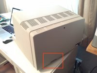
My current Model 4 looks identical but the bottom case does not have that cutout.

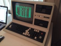
Here are pics of my old Model 4 with the different bottom case with the cutout in the back:

IMG_3338S.jpg
IMG_3337S.jpg

I thought I purchased it back from the original buyer, but it turns out he must have had more than 3, because I got back an entirely different Model 4 along with another... but neither was the one I sold him originally.
 
Just realized I accidentally typed 4D earlier in the thread ... it's not a 4D it's a late model 4 with green screen and clustered keyboard (26-1069)
 
Back
Top