VERAULT
Veteran Member
So I had a big Tandy haul a couple weeks ago. In the haul were some model II and floppy expansion units. There was some damage I assessed when picking them up that was obvious like a smashed Floppy fuse holder and a top cover that was not mating or staying in place but all in all they were intact.
This thread will be about the worst of the bunch. When I got it home and attempted to power it up I got rolling static on the CRT and no typical post lights on the system or floppy drive. The CRT has some minor burn in. The system was either used in an industrial area, or seen a lot of use... Or both. It was completely full of black soot covering everything inside with accompanying thick layers of dirt and dust especially around the lower 120mm AC fan.
I poked around for voltages and noticed there was no 5V rail, and the 24V rail was reading 27.8V.
So I guess we will start with the power supply. Ill be honest my first model II only needed minor work so I never had to really delve too deep into the system. Im sure the tandy technicians has a sure fire plan to take these things apart and put them back together but I couldn't find any disassembly instructions online. I went in blind. I can honestly say you need to practically disassemble the entire system just to get to the power supply and CRT board. Heck I had to unbolt the CRT chassis as well. Not only that this thing was built in a way that implied it was never meant to be taken apart to this degree. My impressions were someone built up a prototype and the higher ups say "Good ship it as-is".
Before doing a repair I needed to wash everything. Metal Chassis, Plastic housing, and all the boards, psu and CRT board. They were pretty bad.. Even gave the CRT a nice cleaning to remove the black grime caked on everything.
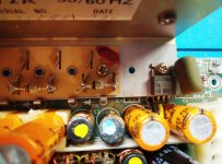
So the psu is clean lets find out why there is no 5V rail. The Suppression cap is badly cracked of course so thats going to need replacement.
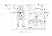
Here is the model II psu schematic

The fuse tests fine, q1 tests fine, My suspicion was IC1 or SCR1. I de-soldered IC1 first and tested D15 (D15 tested fine). My component checker showed no life coming out of IC1. I think thats our first failed component. IC1 is an LM320T-12.


According to TI: https://www.ti.com/lit/ds/symlink/l...-digikeymode-dsf-pf-null-wwe&ts=1715352752854 the LM-320T-12 is a 3 Leg NEGATIVE voltage regulator. So am I barking up the wrong tree concerning the 5v rail?
The LM320T-12 is obsolete. Should I look for NOS or buy one of the substitutes digikey recommends?

Ill wait for some responses before I make an order.
In the meanwhile I guess I will test CR1 next.
This thread will be about the worst of the bunch. When I got it home and attempted to power it up I got rolling static on the CRT and no typical post lights on the system or floppy drive. The CRT has some minor burn in. The system was either used in an industrial area, or seen a lot of use... Or both. It was completely full of black soot covering everything inside with accompanying thick layers of dirt and dust especially around the lower 120mm AC fan.
I poked around for voltages and noticed there was no 5V rail, and the 24V rail was reading 27.8V.
So I guess we will start with the power supply. Ill be honest my first model II only needed minor work so I never had to really delve too deep into the system. Im sure the tandy technicians has a sure fire plan to take these things apart and put them back together but I couldn't find any disassembly instructions online. I went in blind. I can honestly say you need to practically disassemble the entire system just to get to the power supply and CRT board. Heck I had to unbolt the CRT chassis as well. Not only that this thing was built in a way that implied it was never meant to be taken apart to this degree. My impressions were someone built up a prototype and the higher ups say "Good ship it as-is".
Before doing a repair I needed to wash everything. Metal Chassis, Plastic housing, and all the boards, psu and CRT board. They were pretty bad.. Even gave the CRT a nice cleaning to remove the black grime caked on everything.
So the psu is clean lets find out why there is no 5V rail. The Suppression cap is badly cracked of course so thats going to need replacement.
Here is the model II psu schematic
The fuse tests fine, q1 tests fine, My suspicion was IC1 or SCR1. I de-soldered IC1 first and tested D15 (D15 tested fine). My component checker showed no life coming out of IC1. I think thats our first failed component. IC1 is an LM320T-12.
According to TI: https://www.ti.com/lit/ds/symlink/l...-digikeymode-dsf-pf-null-wwe&ts=1715352752854 the LM-320T-12 is a 3 Leg NEGATIVE voltage regulator. So am I barking up the wrong tree concerning the 5v rail?
The LM320T-12 is obsolete. Should I look for NOS or buy one of the substitutes digikey recommends?
Ill wait for some responses before I make an order.
In the meanwhile I guess I will test CR1 next.
Attachments
Last edited: