• Please review our updated Terms and Rules here

TRS-80 model iii

Gary C

Veteran Member
Joined
May 26, 2018
Messages
2,302
Location
Lancashire, UK
Quick question

We have a model 3 on the bench and with the diagnostic rom, it all seems to be fine, however the U104 ROM when read, x00 contains x25 rather than xF3 from the image online, all other locations are fine. As F3 is DI disable interrupts which looks like the first thing you would have in the bootrom it looks like a single bit of bitrot means this ROM is toast.

Is a MCM68766 a suitable replacement EPROM ?

Its the setting I used to download the image from the ROM to check
 
The model 3 contains 14K of ROM (in Model III Mode) divided into:
U104 ROMA MCM68A364 8K Manuf Part Number 8041364 0000-1FFF = 8192
U105 ROMB MCM68A332 4K Manuf Part Number 8040332 2000-2FFF = 4096
U106 ROMC MCM68A316 2K Manuf Part Number 8040316B 3000-37FF = 2048 less 37E8-37E9 = 0xFF

The Original U104 ROM should match a MCM68A364 and can be replaced with a MCM68766 as it is
Pin for Pin compatible. (I've used the MCM68766 to replace my Ver 1.1 ROM's with Ver 1.3 in
My TRS-80 Model 1.)

There shouldn't be any issues.

I've attached the Other two ROM Documents (4K & 2K) in case you wanted them.

Larry
 

Attachments

  • MCM68766.pdf
    512 KB · Views: 4
  • MCM68A364.pdf
    4.5 MB · Views: 1
  • MCM68A332.pdf
    3.3 MB · Views: 3
  • MCM68A316A.pdf
    6.1 MB · Views: 3
cheers

Though, I have just taken a U104 rom out of another model III and it has the same first byte difference, it works fine in the (diskless) model III but not in this one.

More thought required

So the diagnostic rom reports no problems with VRAM or the Main RAM and obviously it can read U104. Shame it doesnt do ROM checksums like PETTESTER.

Need to know the startup sequence.
 
Here is what I have for the first part of 8041364.U104 (Model 3 ROM)
Code:
00000000   F3 AF C3 15  30 C3 00 40  C3 00 40 E1  E9 C3 12 30  ....0..@..@....0
00000010   C3 03 40 C5  06 01 18 2E  C3 06 40 C5  06 02 18 26  ..@.......@....&
00000020   C3 09 40 C5  06 04 18 1E  C3 0C 40 11  15 40 18 E3  ..@.......@..@..
00000030   C3 0F 40 11  1D 40 18 E3  C3 12 40 11  25 40 18 DB  ..@..@....@.%@..
00000040   C3 D9 05 C9  00 00 C3 74  06 CD 2B 00  B7 C0 18 F9  .......t..+.....
00000050   11 E5 41 18  BE 11 ED 41  18 C1 11 F5  41 18 BC 00  ..A....A....A...
00000060   C3 FB 01 20  FB C9 C3 39  30 C3 52 04  11 1D 42 18  ... ...90.R...B.
00000070   AA 00 C3 CC  06 11 80 40  21 F7 18 01  27 00 ED B0  .......@!...'...
00000080   21 E5 42 36  3A 23 70 23  36 2C 23 22  A7 40 11 2D  !.B6:#p#6,#".@.-
00000090   01 06 1C 21  52 41 36 C3  23 73 23 72  23 10 F7 06  ...!RA6.#s#r#...
000000A0   15 36 C9 23  23 23 10 F9  21 E8 43 70  31 F8 42 CD  .6.###..!.Cp1.B.
000000B0   8F 1B 00 00  00 21 05 01  CD A7 28 CD  B3 1B 38 F5  .....!....(...8.
000000C0   D7 B7 20 12  21 4C 44 23  7C B5 28 1B  7E 47 2F 77  .. .!LD#|.(.~G/w
000000D0   BE 70 28 F3  18 11 CD 5A  1E B7 C2 97  19 EB 2B 3E  .p(....Z......+>
000000E0   8F 46 77 BE  70 20 CE 2B  11 14 45 DF  DA 7A 19 11  .Fw.p .+..E..z..
000000F0   CE FF 22 B1  40 19 22 A0  40 CD 4D 1B  21 11 01 C3  ..".@.".@.M.!...

I thought I had a checksum program for the TRS-80 Model 3, but if I do I can't locate it.

If you can load TBUG or TASMON you can Move a ROM's contents to RAM and VERIFY the
first few bytes. I've used TASMON loaded high in RAM to save the ROM.


Larry
 
Last edited:
I have read out the first bytes of the ROM using my programmer and the first two bytes are showing as

25 AF

but all the rest are the same. As F3 opcode is DI, to disable interrupts and 25 is DEC H, F3 looks like the right Opcode.

00000000 F3 AF C3 15 30 C3 00 40-C3 00 40 E1 E9 C3 12 30 ....0..@..@....0
00000010 C3 03 40 C5 06 01 18 2E-C3 06 40 C5 06 02 18 26 ..@.......@....&
00000020 C3 09 40 C5 06 04 18 1E-C3 0C 40 11 15 40 18 E3 ..@.......@..@..
00000030 C3 0F 40 11 1D 40 18 E3-C3 12 40 11 25 40 18 DB ..@..@....@.%@..

against

00000000 25 AF C3 15 30 C3 00 40-C3 00 40 E1 E9 C3 12 30 %...0..@..@....0
00000010 C3 03 40 C5 06 01 18 2E-C3 06 40 C5 06 02 18 26 ..@.......@....&
00000020 C3 09 40 C5 06 04 18 1E-C3 0C 40 11 15 40 18 E3 ..@.......@..@..
00000030 C3 0F 40 11 1D 40 18 E3-C3 12 40 11 25 40 18 DB ..@..@....@.%@..

Dont think its my programmer but its odd that two ROM's have the same issue and one machine works (but is diskless)

I have an EPROM on order and will try it to see but it is strange.

Just thought, what I need to do it check the working machine and PEEK the first two locations just in case its my Programmer but with a 2532 installed with the diagnostic, it doesn't show any issues with RAM. Probably need to extend the diagnostic.
 
Well that was a herring so red you could stick a tail on it and call it a fox.

Drive 0 has a speed controller fault so it never returned valid data

I forgot you could press break to drop into basic, and that worked.

Pokeing and peeking the disk controller seemed to work. Took the drives out and the boot disk is running at full speed (or nothing occasionally) and my boot disks were faulty.

Swaped drives and disks and it now boots.

Strange about byte at address 0 not matching though.
 
Gary,
If your Faulty RPM board is on a Tandon TM-100 Floppy Drive, remove the RPM Board from
the Tandon TM-100 and look at the two small Caps on the RPM board. They tend to leak acid
that eats up the PCB traces, making the RPM board faulty.

If the RPM Board(s) have PCB traces missing I can repair the board with some copper
hollow rivets, and a bit of hookup wire. New caps will make it work fine again. I test them
on one of my SPARE drives.

I've repaired several.

Larry
 
The tandon boards I have repaired before but these are TEAC FD50A's and the speed controller is making my head itch

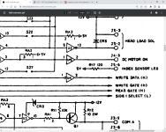
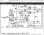
The motor on signal comes from a 7417 which is a driver with an open collector output but this then connects to the speed controller circuit thus

1688196730560.png1688192106695.png

Not sure where the current the driver sinks is coming from, must be IC1. Both drives run intermittently though one when it runs doesn't regulate speed, but both at first run and the working one runs fine and boots, but then they both refuse to run or just stutter and stop. Weird.
The circuit is more complex than the typical Tandon speed controller and I can't find any info on IC1.

The motor on signal is present at pin 1 of U15, but nothing is being seen at pin 2 no matter the state of pin 1.

Looks like I need to replace both drives.
 
Last edited:
And just found this nugget on here from an old post

"Those Teac FD-50 drives are very old and were originally used by Radio Shack in export Model I 26-1160 and 26-1161 240V drive units.

They are not a good choice for the Model III because they only step at 30ms, and the operating systems for the Model III are set up to step at 6ms. The upshot of this is that the boot track will read, show the sign on and then not proceed. Displayed Video, who would have supplied this upgrade back in the day would have supplied special patched versions of TRSDOS or Newdos to step at 30ms. If you've lost those original disks then copies of normal Model III operating systems won't work properly."

So it sounds as if they are crap anyway and not worth repairing.

So I think the best direction to go in is a Gotek with a 3d printed frame and avoid all the problems.
 
I am almost done with the Model III TRSDOS disassembly, and from what I have learned it would not be that difficult to patch TRSDOS v1.3 to run at 30ms. The overwhelming majority of the time, Disk I/O is done by calling back to routines in SYS00/SYS, but there aren't that many other times it is called. What would need to happen is all FDC command masking would need to have bits 1-0 changed from 00 (6 ms) to 11 (30 ms).

But TRSDOS v1.3 isn't very good, and all being equal, swapping out the drive is probably the much better choice.
 
Back
Top