| VCF West | Aug 01 - 02 2025, | CHM, Mountain View, CA |
| VCF Midwest | Sep 13 - 14 2025, | Schaumburg, IL |
| VCF Montreal | Jan 24 - 25, 2026, | RMC Saint Jean, Montreal, Canada |
| VCF SoCal | Feb 14 - 15, 2026, | Hotel Fera, Orange CA |
| VCF Southwest | May 29 - 31, 2026, | Westin Dallas Fort Worth Airport |
| VCF Southeast | June, 2026 | Atlanta, GA |
-
Please review our updated Terms and Rules here
You are using an out of date browser. It may not display this or other websites correctly.
You should upgrade or use an alternative browser.
You should upgrade or use an alternative browser.
Trying to get a 3.5" floppy to work with FDC+
- Thread starter alank2
- Start date
Mike has tested his 55GFR's with the index pulse interrupted and has had no errors, just a performance hit, so that doesn't explain the issue I am having with the MPF920's. My drive 0 seems better than the drive 1, but both have had the issue which is that bdos reports a bad sector. Drive 1 has the problem maybe 10X-20X drive 0. Drive 0 very rarely has it, but has had it.
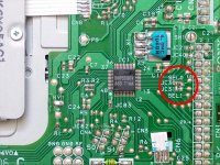
One question I have is that pin 2 that SH1 normally bridges also need to be taken low. I connected a jumper from the left side of SH1 to ground, but I somewhat recall pin 2 being mentioned as a density selection of some type. In the pcb there is a JC21 and JC40 that are near it. Maybe JC21 is a solder jumper to that pin 2 as well. Might it need to be grounded too?
Drive 0 is 359.50 rpm and drive 1 (the worse drive) is 359.29 rpm. Both drives have been cleaned with a cleaning disk.
Attachments
glitch
Veteran Member
Could density select be part of this issue?
You definitely want to make sure you're running at 360 RPM with high density forced, if you're writing low density to HD media, it'll cause problems.
Yep, found that out. I tried to format/copy a low density disk and it didn't even get started with it. I think it might be a drive issue specifically. I copied a disk from drive 0 (the good one) to the drive 1 (the troublesome one) and then drive 1 was reading the disk fine and yet it wouldn't boot from drive 0. I did a format test on both before converting them to 350rpm, but that was each drive formatting its own disk. Could it be an alignment issue? When I was looking at the read channel on them both with a scope last night, they both seemed to have the same amplitude, but I'm not sure which disks were in which drives. I've got more drives, so I'm going to convert another to 360rpm and see how it does. What else besides alignment would cause one drive to not read another's disk? Both are running very near 360rpm.
deramp5113
Veteran Member
Both drives have been cleaned with a cleaning disk.
Dirty heads could certainly be a cause for the variance in performance you're seeing between drives. Unfortunately, cleaning disks do a very poor job compared to manually cleaning with a q-tip and alcohol. Unfortunately, the manual technique got increasingly more difficult as drives shrunk from 8 inch to 3.5 inch.
Mike
I saw someone clean the heads on it, so I could do the q-tip method carefully on them.
I wondered too, could the track buffered CP/M be less demanding of the type of issue causing the problem? In other words, could the more random access of sectors in the mits version expose the problem more easily.
I wondered too, could the track buffered CP/M be less demanding of the type of issue causing the problem? In other words, could the more random access of sectors in the mits version expose the problem more easily.
After a lot of help from Mike (thank you Mike!), the rpm consistency is problematic for at least 2 of the 3 drives I've tried, and the third is probably just waiting to have a problem though it mostly works. The problem happens when there is heavy seeking across the entire disk. That is issue #1 and probably the biggest issue. Issue #2 is the way that the drive hides its index pulse when seeking. I found a pin coming off the IC connected to the ribbon cable going to the drive motor that has an index signal (inverted) that doesn't go away so I disconnected the main ic's index signal by cutting a track and then used a mosfet to as an open collector driver for this new always present index signal. One problem is that when the motor isn't running, it takes the index low, and also it works when the drive isn't selected, so those are two problems I'd have to solve with a tiny miniboard with some logic on it. I _could_ do that and always having an index signal reduce the error, but not enough. The real problem is the rpm variance under heavy seeking. I replaced my somewhat longish 5' mini grabber 20AWG cables I was powering the drive with (they say they can handle 5A) with a short heavier gauge power cable, but it did not change the situation. Here is an example of index to index measurements under heavy seek:
166.897056 ms
166.461184 ms
166.500912 ms
166.570320 ms
166.421032 ms
166.898144 ms
166.616304 ms
The highest/lowest is 166.898144/166.421032 or 0.29% difference.
The difference between the highest/lowest is 0.477 milliseconds.
I am guessing that 477*31/32 or 462 us out of place on that last sector. Mike says the Altair 8” layout is extremely tight and allows less than +/-200us of sector timing variance.
So, for any hope with these drives, I need to improve the rpm stability. I have one drive that is better than the other 2 I've tried, and I have 3 more I have not modified for 360 rpm operation so they are untried at this point. These drives are from 2003/2005 so perhaps their capacitors are less than optimal. I wonder if the variance is caused by the current draw of the stepper or something else. Could bolstering part of it with a larger capacitor mitigate that issue and improve rpm stability?
I've got a very positive follow up on this, Mike has extended his firmware to deal with less than ideal drives like the ones I have. Out of the 6 drives I have, only one of them is outside of a range that will work at this point. (The reason is that its index sensor alignment is quite a bit different than the other drives I have, it could format and use its own disks, but it would have problems sharing with other drives. It looks like the motor assembly is mounted on a module inside the drive (and this assembly contains the index sensor), so I'm going to even try to adjust the 1 bad drive to see if it can be imprvoed). Anyway, Mike has extended his firmware to deal with drives that stop their index pulse and then it gracefully recovers once the index pulse becomes stable again. This change has solved all the issues I was having and now I have a pair of 3.5" drives that are working perfectly. Woo hoo!
If anyone else tries to do this, one thing you may have to do is check the drive's index signal timing against each other. I've got 6 of these drives and I called drive 0 my reference drive, so these values are the other drives vs. drive 0:
drv0 - 0us
drv1 = +57us
drv2 = +289us
drv3 = - 42us
drv4 = 0us
drv5 = +25us
I had been testing with drv0 and drv1 and Mike's enhancements to the firmware has drv1 working fine with a disk formatted with drv0. There is about 200us of flexibility in the 8" 330K format.
drv4 is the same as my drv0 so it is the one I plan to use in a dual drive configuration, but I'll bet drv3 and drv5 would also work perfectly as well. I will test them, but have not yet.
Today I took a stab and trying to correct the horrible drv2. I took it apart and the motor assembly with index signal is a pcb and the only way to alter the index is to loosen three screws and try to reposition it. This was a lot of trial and error, but I eventually corrected the index error. This wasn't without its challenges because the three screws were very small Philips and strip easily. One of them I had to cut a flat channel into the top of with one of the tiny harbor freight diamond cutting wheels on a cordless drill to be able to loosen. Expecting it to possibly work, I was surprised to find it did not despite the index signal being in the correct place. I then saw it was a track off! When on homed to track 0, it was really on track 1. I tried to adjust the track 0 sensor, but it would only adjust to odd tracks such as 1 or 3, but never 0 or 2. Finally I figured out that there are two screws on the stepper motor and I adjusted that to get to track 0. Once on track 0 I found the edges of track 0 and adjusted the stepper to center. drv2 now also works now!
The only mod that needs to be done to these drives is soldering the side of SH1 towards the front of the drive to ground. There is a capacitor directly above it and the top side of that capacitor is ground (test it!) so a small wire jumper was easy to do. This change will make the drive a 360rpm drive instead of 300rpm.
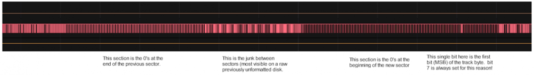
A good test is to write the Burcon CP/M image Mike has, boot it up, and then run crc *.* and see if it does that without an error. The Burcon BIOS isn't so great at retries so if there are problems with a drive, this command will probably expose them. Once that is done, move the disk to a drive B: and run the crc *.* there. If that works you are probably in business, but if it doesn't, then you might want to measure the index difference between the drives. This is easy to use with a logic analyzer or oscilloscope. Get a new unformatted disk or bulk erase a disk. This will make it easier to identify the random zone between the sectors. Then format it in your good drive. Then measure the difference between the index signal and the first bit of the track number of the sector. I'll attach a picture of this. You want to measure from the beginning of the index pulse to that starting bit. Then repeat on your second drive and see how much error there is. I would average 4 or 5 measurements from each drive to get an accurate difference.
drv0 - 0us
drv1 = +57us
drv2 = +289us
drv3 = - 42us
drv4 = 0us
drv5 = +25us
I had been testing with drv0 and drv1 and Mike's enhancements to the firmware has drv1 working fine with a disk formatted with drv0. There is about 200us of flexibility in the 8" 330K format.
drv4 is the same as my drv0 so it is the one I plan to use in a dual drive configuration, but I'll bet drv3 and drv5 would also work perfectly as well. I will test them, but have not yet.
Today I took a stab and trying to correct the horrible drv2. I took it apart and the motor assembly with index signal is a pcb and the only way to alter the index is to loosen three screws and try to reposition it. This was a lot of trial and error, but I eventually corrected the index error. This wasn't without its challenges because the three screws were very small Philips and strip easily. One of them I had to cut a flat channel into the top of with one of the tiny harbor freight diamond cutting wheels on a cordless drill to be able to loosen. Expecting it to possibly work, I was surprised to find it did not despite the index signal being in the correct place. I then saw it was a track off! When on homed to track 0, it was really on track 1. I tried to adjust the track 0 sensor, but it would only adjust to odd tracks such as 1 or 3, but never 0 or 2. Finally I figured out that there are two screws on the stepper motor and I adjusted that to get to track 0. Once on track 0 I found the edges of track 0 and adjusted the stepper to center. drv2 now also works now!
The only mod that needs to be done to these drives is soldering the side of SH1 towards the front of the drive to ground. There is a capacitor directly above it and the top side of that capacitor is ground (test it!) so a small wire jumper was easy to do. This change will make the drive a 360rpm drive instead of 300rpm.
A good test is to write the Burcon CP/M image Mike has, boot it up, and then run crc *.* and see if it does that without an error. The Burcon BIOS isn't so great at retries so if there are problems with a drive, this command will probably expose them. Once that is done, move the disk to a drive B: and run the crc *.* there. If that works you are probably in business, but if it doesn't, then you might want to measure the index difference between the drives. This is easy to use with a logic analyzer or oscilloscope. Get a new unformatted disk or bulk erase a disk. This will make it easier to identify the random zone between the sectors. Then format it in your good drive. Then measure the difference between the index signal and the first bit of the track number of the sector. I'll attach a picture of this. You want to measure from the beginning of the index pulse to that starting bit. Then repeat on your second drive and see how much error there is. I would average 4 or 5 measurements from each drive to get an accurate difference.
Attachments
Another update. Mike has released firmware now that can deal with drive that don't always provide the index signal.
I've run into another gotcha with media that I believe is a poor/bad media thing. The location of the track data is extremely important, but I've had a couple of disks that show that their media has "shifted" in relation to the index signal in the same drive. My theory is that the metal hub on the underside is what is used to determine where the index is based on the hole in the metal where it grabs it to spin it, but that this hub somehow isn't solidly attached to the media itself and shifts slightly. I've seen this happen on a couple of no name unbranded disks so far, but am trying some different brands to see if it happens with others too or not.
I've run into another gotcha with media that I believe is a poor/bad media thing. The location of the track data is extremely important, but I've had a couple of disks that show that their media has "shifted" in relation to the index signal in the same drive. My theory is that the metal hub on the underside is what is used to determine where the index is based on the hole in the metal where it grabs it to spin it, but that this hub somehow isn't solidly attached to the media itself and shifts slightly. I've seen this happen on a couple of no name unbranded disks so far, but am trying some different brands to see if it happens with others too or not.
So, I'm giving a final update on this thread. I've found that the 3.5" drives (at least the 6 Sony MPF-920's that I have) have a lot of intra-track rpm variance. Maybe there is a better term for this, but the bottom line is that during a rotation, the rpm speeds up and slows down slightly. Now, I am sure all drives do this to some degree given whatever method they are using to stabilize the rpm, but what I noticed with 3.5" drives is that it speeds up and slows down exactly in the same places around the revolution - and it does this differently for each drive. I can put a disk in my drv0 and write/format it, then measure the distance between the sync bit and where the FDC+ says the HS pulses should be and it is decent, within +/- 15-20 us. Put it in a different drive and they can be as much as 100us off which isn't good enough. The FDC+ is putting the virtual pulses in the right places, it is the on disk data that literally "moves around" depending on which drive you put the disk in.
If you just want to use the 1.5M mode which stores an entire track as a single sector, this works fine. It is the 32 hard sector sectors that just can't be located accurately with the intra-track speedup/slowdowns.
I've ordered a couple of 5.25" Teac 55 GFR's to try next.
If you just want to use the 1.5M mode which stores an entire track as a single sector, this works fine. It is the 32 hard sector sectors that just can't be located accurately with the intra-track speedup/slowdowns.
I've ordered a couple of 5.25" Teac 55 GFR's to try next.
deramp5113
Veteran Member
You’re talking about the ISV (Instantaneous Speed Variation) spec of the drive.
Mike
Mike
Another update - I finally got a pair of 55 GFR's off eBay. The interesting thing is that they have nearly the same issues I was having with the 3.5" drives.
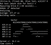
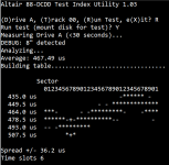
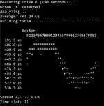
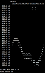
Let me be specific by what I mean by issues. I've written a tool called testindx.com that measures the number of microseconds between the sector good and the first sync bit in the sector. Essentially it measures each sector (0-31) and shows a graph.
I'm attaching two disks each tested in both drives.
The first thing I need to say is that these are repeatable - if I analyze the same disk in the same drive - the graph and results will be the same. Some results are like disk 1 between the two drives, graph is different, but the spread is about the same. disk 2 has a wider spread to where it is messing things up - it would fail trying to read the track in drive B because of what is going on.
The repeatable part of this is what I find interesting. The 3.5" drives did the same thing. I am starting to wonder if part of the direct drive is responsible for this - in other words, for each revolution could there be strong spots and weak spots in that drive where it speeds up and slows down in the same place in the rotation.
Attachments
gertk
Experienced Member
Are there any electrolytic (SMD) caps on those direct drive motor PCB's ?
Is the supply voltage varying also on those drives ? (thin cables, bad contact in connectors etc.)
Is the supply voltage varying also on those drives ? (thin cables, bad contact in connectors etc.)
deramp5113
Veteran Member
...for each revolution could there be strong spots and weak spots in that drive where it speeds up and slows down in the same place in the rotation.
The motor speed is controlled with a servo loop - a feedback control system. By definition it will slow down and speed up as it tries to maintain an accurate average RPM. The rate at which these corrections occur tends to be fairly consistent unless acted on by some external change (e.g., different disk drag, component drift due to temperature, etc.) This speed variation is the major component of the ISV spec of the drive (Instantaneous Speed Variance).
Mike
gertk - I've seen this over various drives, but please tell me what you are thinking about the SMD caps on the motor drive pcb? Power wise I've had various conditions, but usually short decent wires and ample supply.
Mike - It is interesting. Sometimes I can format a disk and its testindx will be very flat as in just 3 slots or so, but if I move it to a different drive it will expand to 6 or 7. Other times if I format a disk, it will look like the first two examples in post 35, both are 6 slots, but the disk was formatted in one of the drives and not the other. Errors occur in the second two examples and I think it is going outside of the timing requirements at that point. I don't think my two disks are very far off on their index calibration. Taking an average of 3 measurements from each drive shows one around 10us different than the other.
Mike - It is interesting. Sometimes I can format a disk and its testindx will be very flat as in just 3 slots or so, but if I move it to a different drive it will expand to 6 or 7. Other times if I format a disk, it will look like the first two examples in post 35, both are 6 slots, but the disk was formatted in one of the drives and not the other. Errors occur in the second two examples and I think it is going outside of the timing requirements at that point. I don't think my two disks are very far off on their index calibration. Taking an average of 3 measurements from each drive shows one around 10us different than the other.
gertk
Experienced Member
gertk - I've seen this over various drives, but please tell me what you are thinking about the SMD caps on the motor drive pcb? Power wise I've had various conditions, but usually short decent wires and ample supply.
.
Older SMD electrolytic caps tend to get quite bad (ESR increases, capacity is lost) and leaky so I would definitely check them.