• Please review our updated Terms and Rules here

Trying to repair a Model 1 that was upgraded to Level II

FozzTexx

Member
Joined
Aug 4, 2013
Messages
23
I recently acquired a Model 1 with monitor but without power supply. I've currently got it on my bench powering it off another power supply. When I tried it out the first time the video wouldn't sync, but I could just make out MEM SIZE? and see that I could type things.

I hooked up Z5 and Z6 to the logic analyzer and found that Z6 wasn't working and swapped it out. Now the video at least fills the screen, but it's not stable and gets waves through it. And worse than that, the computer no longer boots.

I've posted a video of the current state of it here: http://youtu.be/dVuo2yIjf0U
 
FoxxTexx,
I'm wondering if those IC's were in sockets or soldered directly into the Motherboard. I can't remember if mine are in sockets or soldered direct.

If you removed the IC's from the Motherboard, you had to be VERY CAREFUL when removing them to prevent lifting traces. The best method
I've used is to cut the pins from the bad IC, then unsolder each pin with a Unsoldering Iron, then wiggle the pin out of the hole.

I've had to jumper lots of Commodore C-64 traces to new IC's I've soldered into the Motherboard to get them working, after lifting pads & traces.

The good thing is those two IC's are all contained in a very local area and you should be able to scope the signals to see if each Pin has the correct
state.

I wouldn't think anything either of these IC's control would keep the Model 1 from booting, assuming you don't have solder splashes, or cat whiskers
touching other local traces.

You can always try this set of instructions for troubleshooting the Model 1.
http://ts-inc.dyndns.org/Diagnose Repair TRS80 TRS-80 Model 1.html

Maybe it will help you locate the problem.

Here is the Version 2 - Model 1 Technical Reference Handbook:
http://www.google.com/url?sa=t&rct=...w4HQCw&usg=AFQjCNEHUAjcoCt4mtxDqKA7s8ACRalEaw

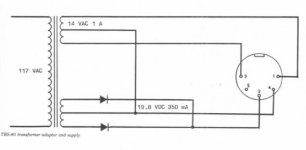
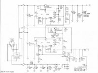
Your External Power Supply just needs to supply +5.00 VDC, +12.00 VDC, and -5.0 VDC. I assume that is what you have wired to the
Model 1 from the External Power Supply.

17.jpg16.jpg


Thanks.

Larry
 
Last edited:
Z5, Z6, and Z57 are all soldered in. I've only replaced Z6 so far, I've hooked Z5 and Z57 to the logic analyzer and they are working correctly. I have a Hakko 808 desoldering gun so removing the chips is a breeze. Once I suck out the solder the chips just fall out of the board. I've double and triple checked though to make sure that all of the connections are still working to all the pins on the chip. I've also made sure all the traces on both sides near Z6 are also still intact.

I'm not sure what's causing the waviness with the video, it seems like I need to get that fixed first and then come back to dealing with why the board stopped booting up.
 
Back
Top