• Please review our updated Terms and Rules here

Victor 9000 PSU

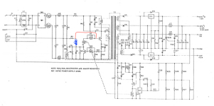
Have been looking at the two ASTEC AA11951 is have and I am noticing some differences between the drawing and the PCB's

Q2's base goes to R7/L4 as shown but their is also a track that goes to R2 which then goes to the mid point of C6/C8.

Will have to draw it out.
 
Ah, it looks as if the only difference is that R2 doesn't connect directly to the anode of D1 but connects directly to the base of Q2.
1709567531915.png
I wonder if this is an error in the drawing, or a different version. It sort of makes sense as it then gives a bias voltage to the base of Q2.
Could someone else verify my tracing out ?
 
And with this, I can see that I am getting no oscillation C9 & coil of T2. C9 open cct.

C9 replaced and PSU running. +5V is high at 6v but unloaded. Need to make up a load bank to test it before connecting to a machine.
 
I can confirm that the drawing doesn't match to my pcb.

From a DC point of view it probably makes no difference.
My C9 was only rated at 85c and quite toasted, being so close to the heatsink, but tested as 288uf, so still functional.
 
That the original drawing doesn't match your PSU ? or my modified drawing doesn't match your PSU ?

Another question to throw out. Does anyone know what Q4 is ?

I believe its something similar to a TL431adjustable voltage reference IC but on its case all I can see is 0100 TI8314 which I can't match up with anything (indeed the 8314 looks suspiciously like a date code)
 
Your version of the diagram matches my board, so is "as built".

The origional drawing is the same in that area as the AA12090 drawing and a few others I checked like the BBC B & B+.

My Astec board has AA 11951 , 100078-02-REV and Dated 8314, so it could also be a design change by Astec if some others are different.
 
Can't find anything except that every Astec PSU of this type seems to use a TL431CP so I imagine its what is in there.
 
Q4 working but Q3 not turning off !

Q3 replaced and PSU no longer crow baring with a load but the 5V is showing 6V. More tinkering required.
 
You could try these load values on page 6 of the attached manual as a guide.
It also has some waveforms.
 

Attachments

  • Astec_AA11320_38W_AA12090_65W.pdf
    3.4 MB · Views: 4
Back
Top