• Please review our updated Terms and Rules here

XT clone motherboard - blown up capacitor + questions

Half-Saint

Experienced Member
Joined
Apr 21, 2004
Messages
322
Location
Ljubljana, Slovenia
After about 20 years of not using it, I picked up my parent's XT and brought it home. As soon as I turned it on, one of the orange caps near the keyboard connector just blew up. It's marked C8 and lies between the keyboard connector and JP4 2-pin connector. The only markings on the caps C6-C9 are 335F and that's it. What would be a suitable replacement?

After desoldering the bad cap, I can still turn the computer on but it reports 'Bad keyboard' during RAM count. Not sure, if that's because the keylock connector is not connected or the cap is the culprit.

This brings us to the second problem. I have no idea what goes where as none of the connectors on the board are labeled. Hence I can't connect power LED, turbo LED, turbo switch or keylock. Does anyone happen to have a manual?

Third question is about the power supply. The orange wire from P8/P9 connector is unplugged and isolated with tape. Why?

Cheers
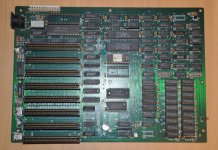
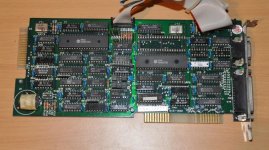
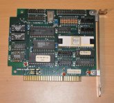
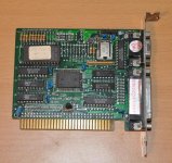
DSC_0640.jpg DSC_0642.jpg DSC_0643.jpg DSC_0641.jpg
 
Last edited:
It is common for tantalum capacitors to go boom.

These capacitors are just used to filter the power a tad, so the machine will work without them. It is easy to find replacements at parts suppliers like Mouser, Jameco, or Digikey. It was probably the one on the - or +12 volt line. It should be the same value as the others, there is a capacitor value chart here: http://www.elecraft.com/Apps/caps.htm

Note that you will need an XT compatible keyboard. Some keyboards have an XT (8088 ) and AT (286) switch on the bottom. Make sure it is set appropriately. Of course, check the connections. It is not likely that the capacitor had anything to do with that.

That is a rather generic Taiwanese motherboard. They came in all kinds of variations and under all kinds of names. You might have to just guess which pins are which. You may be able to find a close enough match on the Total Hardware 99 database: http://www.uncreativelabs.de/th99/
 
Remember when buying replacement capacitors to go with a 50% higher voltage than nominal. Or just buy 25V caps to be safe.
 
Turns out I was lucky and found this by looking at all the mobo pictures on page 1: http://stason.org/TULARC/pc/motherboards/U/UNIDENTIFIED-8088-DES-RIS-TB.html

Placed a jumper over JP3 and the keyboard now works fine.

However, the hard drive controller (HC-100) thinks this is an unformatted drive and wants to format it after POST. It booted fine when I had it connected to a 286 motherboard but the controller was 16-bit WDC. No option to enter BIOS or I don't know how to find it. Anything else I can do?

On a different note, the HDD controller seems to be a flexing when inserted. I did have to push the mobo towards the PSU in order to attach the corner screw but that shouldn't matter, should it?
 
However, the hard drive controller (HC-100) thinks this is an unformatted drive and wants to format it after POST. It booted fine when I had it connected to a 286 motherboard but the controller was 16-bit WDC. No option to enter BIOS or I don't know how to find it. Anything else I can do?
With MFM/RLL style hard drives the low-level formats are different between almost every model of hard disk controller. So when moving a drive from one controller to another, it will appear blank until you perform a low-level format (followed by FDISK and DOS FORMAT). Of course, that will erase all data.
 
There's no way for me to get this going on the XT because, at some point, I had it connected to a different controller? On the 286 board I could simply select 21MB HDD in BIOS and that same drive would boot fine.

So I suppose I'll have to get all of my data off on a different PC and then do a low-level format on the XT?
 
OK but why is that? The HDD controller has its own BIOS. One would expect that the controller would just pick up the drive since it was originally used with it. Plugging the HDD into a dumb (BIOSless) controller shouldn't make a difference. I'd really like to understand how this works and, if possible, avoid moving the files back and forth.

I found the manual on-line but it doesn't mention what to do when the HDD already has a system on it: http://www.minuszerodegrees.net/manuals/Transteque model HC-100.pdf
 
OK but why is that? The HDD controller has its own BIOS. One would expect that the controller would just pick up the drive since it was originally used with it...
Each controller writes it's own (proprietary) LLF to the MFM drives. Unfortunately they weren't standardized back then and for the most part they are not interchangeable. Sometimes you can get lucky -- usually you can't.
 
OK but why is that? The HDD controller has its own BIOS. One would expect that the controller would just pick up the drive since it was originally used with it. Plugging the HDD into a dumb (BIOSless) controller shouldn't make a difference. I'd really like to understand how this works and, if possible, avoid moving the files back and forth.
I do not think there were BIOSless MFM controllers. Probably you were using a MFM controller from another manufacturer in the 286AT but still it had its own BIOS.
 
OK but why is that? The HDD controller has its own BIOS. One would expect that the controller would just pick up the drive since it was originally used with it. Plugging the HDD into a dumb (BIOSless) controller shouldn't make a difference. I'd really like to understand how this works and, if possible, avoid moving the files back and forth.
It is not a really function of the BIOS, it is primarily a function of the controller chipsets.

A "low-level" format specifies how bits are encoded and how these bits are organized in to sectors, and tracks. It may also store bad sector flags, geometry information, and more. This is primarily controlled by the controller chipsets.

Any difference in how this is organized may prevent another controller from understanding it. Even one extra bit field can cause another card to go "wtf is this?".

I don't know specifically what all of these controllers do differently or why, but as I understand it, often the 8-bit controllers store extra geometry information in the low level format.

Add on top of that that there were many vendors all trying to add different features or trying to make things cheaper. So there was a lot of variation in the technology they used.

I do not think there were BIOSless MFM controllers. Probably you were using a MFM controller from another manufacturer in the 286AT but still it had its own BIOS.
IBM's AT hard disk controllers and many hardware compatible clones did not have their own BIOS. In this case, the motherboards BIOS provides support for these cards. Any card that was not hardware compatible with IBMs controllers would require their own BIOS.
 
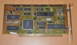
Reading through the documentation of several other WDC MFM controllers, I came across some interesting info. If motherboard's BIOS is used to define HDD parameters, the BIOS on the card is not used and vice versa. I couldn't find the model number or manual for the card that I used with the 286 but here's a picture.

DSC_0644.jpg
 
Back
Top