• Please review our updated Terms and Rules here

Z-80 ROM Monitor for Compupro CPU-Z

NF6X

Veteran Member
Joined
Sep 9, 2013
Messages
1,534
Location
Riverside, CA, USA
I'm getting close to bringing up my S-100 chassis for the first time, populated with a set of Compupro cards. My full card set consists of:

  • CPU-Z
  • System Support 1
  • RAM 17
  • Disk 1
  • Interfacer 4

I think that I would like to start with a ROM-resident monitor for initial debugging, before I try booting up from any floppy disks. So, I figure I should install a ROM-resident monitor in a 2732 EPROM on the CPU-Z for initial bring-up, with banks disabled as needed on the RAM 17 to avoid conflicts. Later, I can disable the ROM bank and switch in RAM instead. Yes, I'm aware of the mods needed on the CPU-Z to use 2732 instead of 2716, as well as the apparent error(s) in the manual on that topic. :)

I'm a bit confused about which Z-80 monitors might be suitable, particularly without needing any patches. It looks like MASTER.Z80 can be used on the CPU-Z, but when I look at the equates in the code, it's not clear to me whether the pre-compiled hex file is compatible with using the System Support 1 for the serial console without any patches. The code seems to be making references to some sort of "propeller" at 0x00/0x01 for console I/O.

Can anybody suggest a suitable pre-assembled ROM-resident monitor that I should be able to use as-is on my CPU-Z card for my initial bring-up? I'd prefer to put off needing to modify and re-assemble anything until I have the whole system up and running under CP/M.
 
I think I should expand on my comment about manual errors while it is fresh in my mind, for the benefit of Compupro CPU-Z owners finding this thread in a thousand years.

The user manual scan indicates that when converting from 2716 to 2732 EPROM configuration, the trace connecting jumper J2(A-B) needs to be cut, and J2(A-C) needs to be connected. However, studying my PCB shows that J2(B-C) would need to be connected instead, and that also agrees with the notes here about configuring the card. It appears to me that pins A and B of jumper J2 are swapped on the real card. That is, on the real card, J5(B) is connected to pin 21 of the EPROM sockets, vs. J5(A) shown as connected to pin 21 of the EPROM sockets on the schematic diagram.
 
You are making this much more complicated than it has to be.

The boards you got from me were all tested and configured. I would hope that the other boards you bought are in the same condition.

You must have made the power cable, and connected and tested the power supply by now.

So, disconnect the power from the mainframe, install the boards in the recommended order in the motherboard, connect the terminal and disk drive cable/s.

Reconnect the power to the mainframe, and hold the Reset button while you turn the power on to the mainframe, and the disk drives. The drive doors should be open, and the disk/s partially pulled out to prevent glitching the disk/s.

When you let go of the Reset button, the drive select light on Drive A: should start cycling on and off. This tells you that the processor, disk controller and memory are working. If you are ready to finish booting up, make sure the terminal in on, depress and hold the reset button, insert the boot disk, and release the Reset button. If all is well, the system will boot up and place the terminal at the Prompt.

Don't modify the Disk-1 floppy controller board, and don't screw with the monitor. It simply is not necessary. The beauty of Compupro components is that they work without any dramatics. Just load and go in most cases (unless someone has screwed with the parts).
 
Yes, I've built the backplane power harness, rewired the AC input to my liking, tested the power supply, cleaned out the dust, and smoke-tested it all with only the least critical board (the Interfacer 4) installed, just in case I made any wiring mistakes. The power supply voltages appear to be present and correct.

Unfortunately, the full system isn't coming to life. I don't see any drive activity after reset. As an experiment, I pared it down to just the CPU-Z, Disk 1 and RAM 17, and configured the Disk 1 to use its software console. I don't get any response from it when I send it a "U" at 300 baud. I was hoping that the autobaud + start-up message would work even if my drives aren't jumpered correctly, so I'd at least verify that the CPU is executing code.

My drives may or may not be jumpered correctly for use with the Disk 1. They're presumably still jumpered as they were when this chassis was scrapped. They're Mitsubishi M2896-63-02U drives, and they don't appear to have the same jumpers that the Disk 1 manual calls out for the M2894-63.

I'll need to begin debugging the basics, such as verifying that the backplane termination isn't blown, verifying that the reset button is actually doing anything, probing for CPU activity, etc. I have no reason to doubt that the boards were fine when I bought them from you (and hopefully still are!), but I'm bringing up a newly-assembled system with some of its components in unknown condition. It's a shame that it doesn't have a blinkenlight front panel! :)

In any case, I want to install a ROM-resident monitor eventually, even if I get the full system up and running without it. I was hoping to find a plug-and-play one to use during initial system bring-up, but I haven't found any so far that appear to support the 2651 UART on the System Support 1 board.

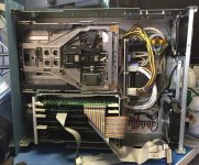
This has been a fun project so far, and I hope it won't be to hard to get to the finish line. Here's a picture of the assembled system:

FullSizeRender 5.jpg
 
I had a few minutes to work with the system this morning before getting ready for work. It's not fixed yet, but I did knock down one issue: MWRITE generation was disabled on the CPU-Z by U36 pin 9 being lifted from the socket. The manual states that this can be necessary in systems with a front panel, to avoid contention between multiple MWRITE drivers. But on my front-panel-less system, I believe this would prevent any RAM writes, if my understanding is correct.

I noticed it while probing around the RESET circuit, which also uses a gate in U36. I found that my chassis has its reset button implemented as an SPDT switch which pulls RESET up when not pressed, with a very strong pull-up to +8. I think this is not only unnecessary, but also potentially damaging to everything connected to the RESET line. I disconnected the pull-up wire, and I plan to test out all of the logic touching the RESET bus signal in case any gates got blown. The RESET input gate on the CPU-Z still seems to be functioning, but I didn't have time to test out the other cards' RESET inputs.
 
When you were here, I thought you took a photo of the logic board from a Mitsubishi M2896-63 that was configured for use with Compupro board set. The jumper setup for the Mitsubishi M2894 full height drive is not the same as for the M2896-63 1/2 height drive.

If you need, I can provide the jumper setup for the M2896-63.
 
I'll need to check my computer at home to see if I still have the M2896 picture I took, but I think I know how my drives will need to be jumpered anyway, by comparing the Disk 1, M2894 and M2896 manuals. I don't think I've gotten to the point where drive jumpering is the last remaining issue to solve quite yet.
 
I just got my first successful CP/M boot! Woohoo!

Debugging with an oscilloscope showed that no I/O accesses were occurring on the Disk 1 card. Probing the CPU with a logic analyzer showed that it was getting 0xFF on its first fetch after reset, jumping to the trap at 0x0038 to handle the resulting RST instruction, getting 0xFF there as well, and then continuing to fetch from 0x0038 forever. More probing showed that the Disk 1 was trying to drive its boot ROM contents onto the bus, but it wasn't making it to the CPU. As it turned out, the CPU-Z card was simply configured for use in a front-panel system, and the lack of a driver on bus pin 53 (non-standard signal SSDSBL) meant that U43 on the CPU-Z card never allowed the DI bus to make it to the CPU's data pins. Pulling the jumpers at J6, J8, and J9 got the CPU fetching code from the boot ROM, and the first CP/M prompt quickly followed. Yay!

A ROM monitor probably wouldn't have helped in what turned out to be a job for a logic analyzer, but I'd still like to have one. Maybe I can take one of the other Z-80 ROM monitors I've found and patch it to support the 2651 UART on my System Support 1 card.

I haven't found any signs of damaged reset circuits as I previously mentioned fearing. But I did find that the reset button is very bouncy, so I may add a nice, clean power on reset circuit to my chassis. It's not really necessary, but it would help me sleep better at night.
 
A ROM monitor probably wouldn't have helped in what turned out to be a job for a logic analyzer, but I'd still like to have one. Maybe I can take one of the other Z-80 ROM monitors I've found and patch it to support the 2651 UART on my System Support 1 card.

John's MASTER.Z80 monitor was derived from the Apple/Zapple monitor but has a ton of extra code added to it to support the various S100Computers boards, resulting in either a 4K or 8K size.

If you have your heart set on a monitor ROM, I would go back to the original 2K Apple/Zapple monitor to avoid any need to modify the CPU board. Or take John's code and gut it to remove all of the stuff you don't need..........
 
Thanks for the suggestion. Adapting an original 2k monitor rather than using the heavyweight MASTER.Z80 sounds like a good idea. But I'm inclined to reconfigure my CPU-Z for use with 2732 EPROMs anyway, simply because I have several 2732s and only one 2716. Not that it's a big deal to reconfigure the board, anyway; it was designed to support either 2716 or 2732 EPROMs, after all.

As long as I'm here replying, I've cabled up a backup battery pack and verified that my System Support 1 board's real time clock is working just fine. I'll probably add a Lotharek HXC-1 floppy emulator to the system, with a switch to swap drive IDs 1/2 with 3/4 on the cable so I can easily boot from either the emulator or the real 8" drives, and then transfer stuff between them. I haven't done anything with the Interfacer 4 yet, but that's on my to-do list.
 
Back
Top