• Please review our updated Terms and Rules here

Mini-Omnibus backplane for debug and minimal system

FYI, Figure 15 in the datasheet addresses this concern with an external 2N4036 output stage.

View attachment 1242285
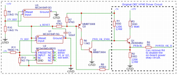
This looks interesting but I'm skeptical about their application note. If RESET (pin 6) is undefined when the voltage is below the reset threshold, then assume "undefined" could mean it's in the wrong state. So, with the voltage low but not zero, the proper state of RESET would be high (actually open collector is off), but if RESET were improperly low (open collector pulling down, then Q1 would be saturated and pull the "System RESET_bar" signal high in the not reset state. I think once the voltage detector produces the wrong state there is not a way to correct it.

I do like that the TL7705 threshold is 4.5V, which is higher than the MC34164, but I think we can adjust the threshold of the MC34164 slightly using an external divider. Here's the schematic for that:
reset circuit v2r05x2.png
 
v2 r05 x2, I think about ready to order PCBs
Has a circuit to detect when +15V is low
Has a divider to adjust the +5V low-voltage threshold higher than 4.27V
Has a TL7705 test circuit
Various clean-up
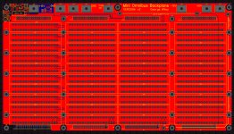
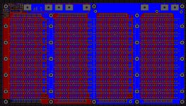
Mini Omnibus Backplane layout Top v2 r05 x2.jpg Mini Omnibus Backplane layout Bottom v2 r05 x2.jpg

Schematic:
 
This looks interesting but I'm skeptical about their application note. If RESET (pin 6) is undefined when the voltage is below the reset threshold, then assume "undefined" could mean it's in the wrong state. So, with the voltage low but not zero, the proper state of RESET would be high (actually open collector is off), but if RESET were improperly low (open collector pulling down, then Q1 would be saturated and pull the "System RESET_bar" signal high in the not reset state. I think once the voltage detector produces the wrong state there is not a way to correct it.
I'm not advocating to change your design :-}. But I think that your interpretation regarding the behavior of the TL77xxA is incorrect in two respects -- and at this stage experimental evidence is lacking but ...

(FWIW, perhaps you are looking at the older data sheet from March 2012 "Supply Voltage Range: 2 V to 6 V" which are the not-A parts, and I'm looking at the newer data sheet from September 2016 "supply voltage range of 3.5 V to 18 V" which are the superseding A parts?)

First, IMO Figure 1 is a bit obtuse, designed for marketing more than engineering:
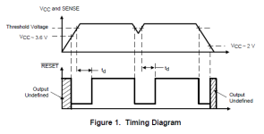
1654836243400.png
Note that the label on the upper ordinate conflates Vcc with Sense. IMO their point is that the IC requires a minimum of 3.6v in order to operate properly (so stated in the prose); it's necessarily the case that the output signals can't exceed applied Vcc and as the table in 6.5 identifies that Voh MIN is Vcc-1.5v this means that it's simply not possible to achieve Voh as the "high" logical value that they define (>3.5v) when Vcc < ~3.6v.

The lower ordinate is a logic-value (in their MIN/MAX terms) rather than a voltage -- and if graphed as a voltage it necessarily is constrained on the high-side as a ramp. See Figure 9, which is an honest plot of voltage, rather than logic value:
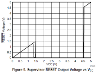
1654836810600.png
So "undefined" means that Vol (MAX 0.4v) isn't being met either; the output exceeds the logic-zero max and is less than the logic-one min. It's still a quite well-known voltage; it's just an analog value that can't be interpreted digitally using their MIN/MAX definitions. There is no "state" here.

Note that while the ~RESIN input uses TTL logic levels, the pair of RESET outputs use a different definition of logic levels. The pair of RESET outputs operate in analog-mode below ~3.6v, and in digital-mode above that Vcc. And digital-mode is IAW their definitions of logic-zero and logic-one.

We need to keep in mind that these circuits aren't being supplied by a nice meets-spec Vcc while only SENSE is fluctuating ... which at least for me makes this all a bit of a head-scratcher!

Second, I don't agree that the presence of hysteresis operating around the Vt (4.55v) has any bearing on the behavior of the device when Vcc < 3.6v. I don't think that there's any "latching" going on. Furthermore I can't imagine a common part like this being designed and sold to behave as badly as you describe :-}! It would _not_ be fit-for-purpose, IMO. What sort of product designer would contemplate using a part that was in effect metastable at power-on, ending up in an arbitrary latched state precluding further use as a supply voltage supervisor?

It seems to me that the point to the PNP-follower is to ensure that the (output) System ~RESET signal -- based on the RESET curve in Figure 10:
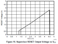
1654838106600.png
-- conforms to TTL(ish) logic levels in the low-Vcc setting by ensuring/letting the output System ~RESET rise directly with Vcc (thus "as one/true as it can be", removing the low-Vcc "notch" in Figure 10) until RESET "snaps over" to ~0V (logical zero/false) and Q1 is driven into conduction, the objective being to avoid the logical No Man's Land that the TL77xxA can't avoid on its own under low-Vcc conditions. System ~RESET simply "floats" upwards based on rising Vcc and the characteristics of the input of the downstream device(s) until Q1 snaps into conduction. With full Vcc achieved, Q1 then operates as a simple inverter (and all is well in the world :-}).

My guess is that the TL77xx designers felt that the cost of incorporating the additional circuitry on-chip outweighed customer-value in common use-cases (MCU ~RESET, which are typ. more forgiving inputs than strict/simple TTL)? However they illustrated two designs for potential use in situations with more exacting requirements, e.g. "strict TTL" -- which is the use-case that concerns us here.

Perhaps I am completely misunderstanding the design and behavior of the TL77xxA and the PNP-follower, in which case please do set me straight ... because I'm "not with you" as yet :-}.
 
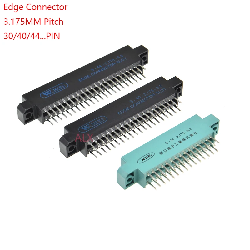
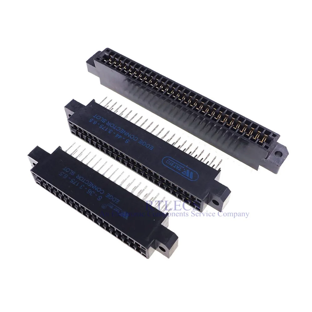
The connectors with 0.125" (3.175 mm) contact spacing available from AliExpress aren't the nice deep slot connectors as on a real DEC backplane. They're more shallow and allow a wider "tounge" (the part with the gold fingers). I made a pair of acrylic strips with a kerf every ½ inch that holds the boards a little more steady. To make the plug-in boards align well it's necessary to use either dual 40 or dual 43 pin connectors, cut of both sides, remove some pins and install shims between the A and B, and between C and D. I learned this trick from the Douglas Electronics Omnibus module extender. The shim is a very simple piece designed using Microsoft 3D builder. I had some shims 3D printed and they fit nicely. I can share the STL file. There are two sources for for the same connector (the 2x40 or 2x43, again, some modifications are required):
Thanks for the links. I don't know what I did but never was able to find those. So I immediately ordered a few. They just arrived today, as you mentioned they are not as shallow and allow for a wider tongue, but that's no issue here. The contact is the same and for the tongue I plan to make the opening narrower by glueing some small sticks to each head-end. They look like they are of a decent quality and are the perfect start for my small Q-Bus backplane project (5 x dual). I ordered just enough 2 x 18 connectors.

Peter
 
This thread has somehow gone cold for the past month.
George - are you still planning to release the gerbers and/or design files for your nice mini-Omnibus backplane?
I would love to build one and start using it. :)

Thanks for your work on this.
Tom
 
This thread has somehow gone cold for the past month.
George - are you still planning to release the gerbers and/or design files for your nice mini-Omnibus backplane?
I would love to build one and start using it. :)

Thanks for your work on this.
Tom
Tom and Paul, thanks for following up. Things have progressed but rather slowly. My time has been a bit diluted with business and personal travel. Plus I've started restoring an 8/L, and have been building a version of the Stearns tester to test 8/L boards. So, there are too many fun projects and not enough time. At the beginning of the first trip I ordered backplane PCBs from JLCPCB so they'd be waiting for me when I returned home. JLC did most of the SMT assembly of the POWER_OK parts in the upper left corner of the board to save some build time. I have all of the parts and hardware now, just need to build it up and test it.

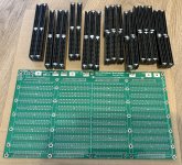
Here's the PCB with the connectors that have been cut to size and have the shims installed.
Backplane PCB and Connectors 50pct.jpg
Details of cutting connectors and installing the shims are in this post:

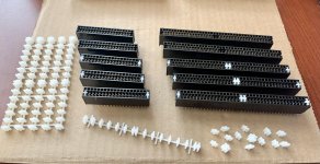
Here's a photo of an entire rack of shims (on the left). This rack of shims is for 10 slots costs about $1.50 for printing at JLCPCB. They're rather easy to separate with diagonal cutters.
shims and connectors.jpg
 
Thanks George.

The board and the connectors with the shims look great.
What did you use to cut the connectors?

I have now placed the order for the connectors.
I went with the second supplier which is a bit more expensive, but the first one ships black or green (different manufacturer) at random.

As JLCPCB has a minimum order size of 5 I wonder if you have one board and a set of shims spare for sale?

Thanks again.
Tom
 
As JLCPCB has a minimum order size of 5 I wonder if you have one board and a set of shims spare for sale?
Very interested as well Tom; at least I'm located on the same continent :->. Sure looks nice.

Hoping that you start a thread on your work on the Stearns tester (and 8/L). Which variant are you building (https://so-much-stuff.com/pdp8/repair/fc-tester.php)? I also have an 8/L (first love!) to restore. Reformed PS capacitors and finally got it properly racked last week, but for the moment that restoration effort is paused. So your effort most timely and interesting!
 
The board and the connectors with the shims look great.
What did you use to cut the connectors?
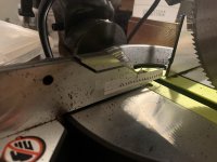
Thanks. I used a small 7 1/4 inch power miter saw with a 140 tooth blade. The photo below shows a guide taped to the saw to help align the connectors. Notice the icon warning to not put your hand there, so a clamp is necessary to secure the connector while cutting. Small marks from the connector pins are visible on the paper guide. I didn't have the marks perfectly aligned and adjusted the position of the connector early in the cutting process, which made the small dots to the right of the larger marks.
miter saw alignment guide.jpg
I have now placed the order for the connectors.
I went with the second supplier which is a bit more expensive, but the first one ships black or green (different manufacturer) at random.
I wondered about that. I bought my connectors, a combination of 2x40 80-pin connectors and 2x43 86-pin connectors, from the supplier that has a photo of two black connectors and one green. I assumed the green connector was the 2x15 30 pin connector but maybe I just got lucky and received all black connectors.
As JLCPCB has a minimum order size of 5 I wonder if you have one board and a set of shims spare for sale?
I do have some extras. PM me and maybe we can figure out something.
 
Very interested as well Tom; at least I'm located on the same continent :->. Sure looks nice.
Haha, true. USPS to MD is probably easier. PM me also. Can probably figure out something for Perth and Silver Spring.
Hoping that you start a thread on your work on the Stearns tester (and 8/L).
Can do that. So far I've only powered up the tester board and confirmed that the voltages are present and LEDs light up. I have parts but progress is slow. Have loaded the code into Microsoft Visual Studio to play with it a bit.
I made a variant of the StearnsMTvrs version of the Warren Stearns tester... same netlist but just some adjustments in the PCB layout. This is the PCB version of the Stearns tester with modifications for the MThompson FTDI C232HM interface. Thinking about controlling it with an ESP32 (Arduino).
I also have an 8/L (first love!) to restore. Reformed PS capacitors and finally got it properly racked last week, but for the moment that restoration effort is paused. So your effort most timely and interesting!
You're ahead of me. So far I've reformed the three big electrolytics in the power supply and tested the +5V regulation using a DC lab supply as the power input. Haven't applied AC voltage to it yet. Oh, also verified the OVP. Also built Roland's "Crowbar_PDP8-L" board ( https://github.com/Roland-Huisman/Crowbar_PDP8-L ) and tested it, but haven't yet attached it to my 8/L.

No rack yet here. The chassis sits on a dolly on the floor of my office and the power supply is removed and on the bench.
 
A set of design files for "Mini Omnibus Backplane v2" are now available in the following repository in github:
There are still some more things to verify but the following has been checked out:
  • voltages checked on every supply voltage pin of every edge connector
  • the POWER OK circuit has been evaluated
  • a minimal system ran maindec-08-dhkma-d-pb with 32 KW successfully for a few hours
Thanks for the update. This sounds very promising.
What did you use to power the backplane?
 
What did you use to power the backplane?
I'm using three NicePower adjustable bench supplies for +5 +15 -15, and a 9V power adapter (found in my junk box) for to power the 8/E front panel lamps (the "yellow" wire). I'm kind of nervous about not having OVP in this present temporary configuration.

One possibility is to use the board that I built that detects over and under voltages that also opens a MOSFET switch in overvoltage conditions. Another possibility is to build three of Roland's OVP for the 8/L and replace the zener diodes in two of the boards so the crowbar trips "comfortably" above 15V.

I built one of these boards for the 8/L so I have some spare boards that I can build up to use with the Mini Backplane.
The Meanwell supplies I decided to use have OVP protection at reasonable levels. It shouldn't be necessary to double up, but one could use Roland's circuit for this.
 
The Meanwell supplies I decided to use have OVP protection at reasonable levels. It shouldn't be necessary to double up, but one could use Roland's circuit for this.
I was looking at the datasheets earlier when you posted the part numbers. I agree, the OVP in these supplies should be sufficient.
I should probably also order the same set of Meanwell supplies instead of using the adjustable bench supplies.
 
I was looking at the datasheets earlier when you posted the part numbers. I agree, the OVP in these supplies should be sufficient.
I should probably also order the same set of Meanwell supplies instead of using the adjustable bench supplies.
Adjustable bench supplies are great ... except that they are adjustable which makes them dangerous even with lock features.
They are also relatively expensive if they are dedicated to a single purpose which doesn't require the adjustability.
Unfortunately I couldn't find a single supply with the right voltage & current mix, but the 3 cheap individual supplies should work well.
I will mount them in a suitable metal box with a small fan.
 
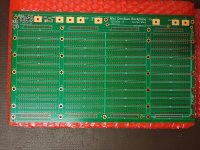
DHL delivered the Mini-Omnibus PCB from JLCPCB. :)
I ordered the "delux" version with 2 mm PCB thickness, 2 oz outer copper weight and ENIG-RoHS finish with PCB assembly of the few surface mount parts.
It worked out quite expensive at US$200 including shipping, but looks pretty good:

IMG_20220823_193356508.jpg

I have also cut all the edge connectors using an electric scroll saw. I started with the original rubbish Chinese blades made by Ryobi. Each blade barely lasted for one edge connector. I then bought some Swiss made blades and cut the remaining connectors with a single blade which still looked like new at the end. Some Chinese stuff is really good, some is garbage and price it not necessarily a guide. The Swiss blades were cheaper (about 70%) than the Ryobi blades.
 
Looks really nice in gold! Scroll saw is a good idea for cutting the connectors. I used the miter saw with rotary blade because it's the tool I have. Little black plastic sawdust bits get everywhere! I'm still finding them on my workbench.

I ordered the "economy version" :ROFLMAO: ... 1.6mm and LeadFree HASL-RoHS. Cost with shipping was about a third of the deluxe, but doesn't look nearly as nice and solid as yours.

It looks like JLC added some extra rails on the top and bottom, with a v-score between the main board and the rails, maybe to assist them with fab or SMT assembly. Looks like it has tooling holes and fudicials.
The scroll saw is not ideal because you have to hand guide the part while sawing. I set the saw to its lowest speed and used magnifying goggles and good lighting and managed.
I think an electric miter saw with fine blade with 100+ teeth would make it much quicker and require less concentration, but I don't have such a saw and it made no sense to spend another $300+ for something I won't use much if ever.

Tomorrow I will use a file and sand paper to clean up the cut edges. The spacing for the socket screws is quite tight so I will lightly bevel the corners.

Sometimes this week I should also get the 6 mm acrylic sheet to mount the board onto.

I noticed the extra rails, but they should break off without too much effort.
 
Back
Top