RetroGadgetMan
Experienced Member
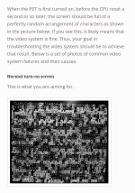
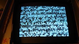
Hi after debugging the video logic with help from some people here which I am really grateful for we now have a garbled screen.
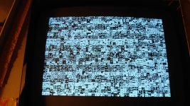
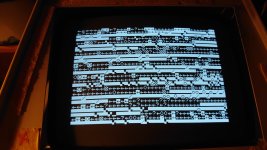
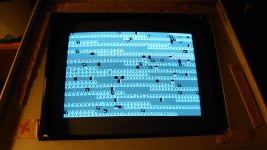
Character set has been replaced and I now get the following image pic 1.
Sometimes some of the characters will change if I press down on the board in various places or even flicker indicating a bad socket or maybe a bad trace.
I have cleaned all the sockets which made no difference.
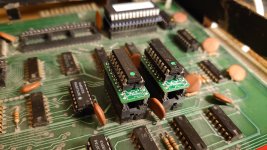
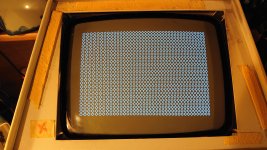
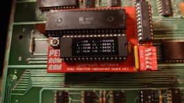
Pic 2 shows the tynemouth pet rom ram substitute.
This can be configured to replace either the rom or ram or both and allso contains basic 1 2 and 3 selected by dip switches.
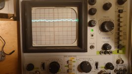
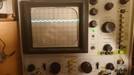
Pin 7 of the CPU with this rom ram board is at hi lo and pulsing.
With the original CPU installed with out the ram rom board pin 7 stays at lo.
Moving forward I think it's best to keep using the rom ram board until we get the correct welcome screen and a flashing curser. Then we can start looking at the rom and ram section.
Character set has been replaced and I now get the following image pic 1.
Sometimes some of the characters will change if I press down on the board in various places or even flicker indicating a bad socket or maybe a bad trace.
I have cleaned all the sockets which made no difference.
Pic 2 shows the tynemouth pet rom ram substitute.
This can be configured to replace either the rom or ram or both and allso contains basic 1 2 and 3 selected by dip switches.
Pin 7 of the CPU with this rom ram board is at hi lo and pulsing.
With the original CPU installed with out the ram rom board pin 7 stays at lo.
Moving forward I think it's best to keep using the rom ram board until we get the correct welcome screen and a flashing curser. Then we can start looking at the rom and ram section.
Attachments
Last edited: