RetroGadgetMan
Experienced Member
Done.That is a fair comment. With RAM and ROM substitution from the ROM/RAM board it would reduce to a bad CPU or decoding issue... and then buffers across to Video RAM.
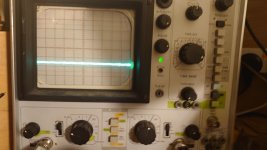
Remove all the RAM and ROM except for the Video RAM and try the ROM/RAM Board... and scope pin 37 and pin 7 of the CPU. Looks like ON ON ON OFF OFF which you have is a good setting.
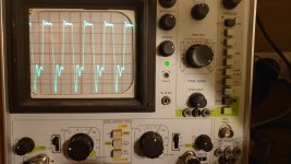
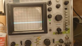
Pin 37 pic 1
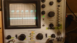
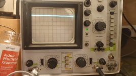
Pin 7 pic 2