• Please review our updated Terms and Rules here

My Rusted PET8032 with busted CRT ...continuous resurrection

RizThomas

Experienced Member
Joined
Jan 2, 2012
Messages
198
Location
Surrey,BC,Canada
3CDF903D-5DEA-4A60-B0E3-0D23C2250B78.jpeg
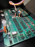
About 2-3 years ago, I decided to buy this PET 8032 locally ( advertised with busted CRT, dead AS IS). It was dirty, case rusted, motherboard shows rusting ic pins, etc. After giving it a thorough cleaning, I tried to see if it powers up, or “chirps”.
Nothing..so I replaced IC sockets for all the essential chips ( cpu, pia, crt controller, ROMs, etc).
I scanned and read every post here in this forum just get some hints where I should proceed. Thanks to The 2 Daves, Giobbi, Hugo ( rest of the community), I learned a lot.

Because sourcing a CRT is next to impossible, I decided to pursue in getting a Composite Video out instead and interface it with modern monitors. Meanwhile I was sourcing also other IC ( 6520, 6522, cpu, 2716 / 2732 eproms)
Then Bitfixer came up with the Romulator.
- - because I will be building NTSC ( with CRTC) composite adapter, I had Bitfixer incorporate 2 of SJGray’s NTSC Edit-ROMs.
With all of these preparations, I proceeded to do all of these test on the 8032. NO Success. NO “Chirping sound”....so it got shelved for a while.

Lately, I decided to un-solder all of the 4116 RAMs, and ( Surprise!!) , it CHIRPED with the Romulator installed but No Video.
— I adapted Hugo’s composite video circuit that was uploaded in one of the threads here...got something —- garbage characters in one line in the middle of the screen.
— so today, I decided to un-solder the 2114 Video RAMS, one turned out faulty ( I tested them by substitution in my C64).
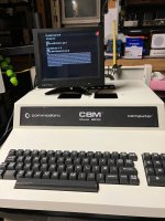
Test showed blank screen, got the Chirp sound. By luck, I found that taking out a 6520 PIA ( keyboard), the BASIC4 boot message came on but no flashing cursor. So, I installed a new 6520 chip. VOILA...now with cursor. But of course, the keyboard was faulty too, so I did some contact keys cleaning, etc.

GOT IT BEAT.....NO....something is wrong
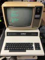
1. Typing any commands returns a Syntax Error
2. Did a Print Statement....returns nothing
3. And once I reach the bottom where it starts to scroll the lines, all previous and next characters changed to garbage character.
I don’t know ATM where to proceed. I may have corrupted KERNAL/BASIC4 in my ROMULATOR ( after all ic substitutions, etc) . I may end up re-programming my ROMulator ( will contact Mike (Bitfixer)).

Any advice is very much appreciated ( Thanks to all 8032 posters here- DAVE(S), Hugo, Giobbi, and others 80CAFC98-5A31-401C-AA8F-D46E4F0F6278.jpeg
 
My gut feeling is that the ROM can successfully WRITE to the video RAM - and the characters display correctly - but can't read correctly from the video RAM.

I would concentrate on getting a copy of my PETTESTER running. You can do this in multiple ways:

1. Ask Bitfixer nicely to incorporate it into into his emulator (if you have a version that doesn't have it incorporated and no way of doing it).
2. Either burn a ROM (or ask someone nicely to burn a ROM for you) with my PETTESTER and swap it for your EDIT ROM.

The first test I do is to test out the video RAM. The code writes all of the characters to the video RAM and then reads them back and checks for equality. However, it is not very good at displaying the erroneous reads. A separate program has been written (by Nivag I think) that writes the characters $00 to $FF into the video RAM and then displays the values in HEX that were read back.

Between the two test programs we should have the means to work out what is going wrong.

Another possibility is to try out TIM.

TIM is a resident machine code monitor within the 8032 ROMs. You activate it by pulling the /DIAG pin LOW and then powering up the PET. With any luck (although not guaranteed of course) you may be able to enter commands into TIM and it may take them. If this is the case, we (you) should be able to write known characters into the video RAM and then read them back to see what you get.

Various options to consider moving forwards.

Dave
 
Thanks Dave,
Could a 2114 ( with different speed) mixed with the original can cause these bad characters. I am sourcing some newer 2114 replacements.
Here are my option which I probably won’t see any actions till next year.
- currently in talks with Mike for Romulator programmer
- source some parts and adapter to burn some ROMs ( will build the 2532-2732 adapters)
- get a 4116 tester and re-source some RAMs

I still would like to get the 8032 without using the Romulator as an option.

BTW...embarrassing
Could you confirm the location (U7 ??) of the PETTESTER and where can I download the .bin / manuals for 8032. I lost my HDD and can’t find it anywhere in my archivez.

Thank you
 
My gut feeling is that the ROM can successfully WRITE to the video RAM - and the characters display correctly - but can't read correctly from the video RAM.

I would concentrate on getting a copy of my PETTESTER running. You can do this in multiple ways:

1. Ask Bitfixer nicely to incorporate it into into his emulator (if you have a version that doesn't have it incorporated and no way of doing it).
2. Either burn a ROM (or ask someone nicely to burn a ROM for you) with my PETTESTER and swap it for your EDIT ROM.

The first test I do is to test out the video RAM. The code writes all of the characters to the video RAM and then reads them back and checks for equality. However, it is not very good at displaying the erroneous reads. A separate program has been written (by Nivag I think) that writes the characters $00 to $FF into the video RAM and then displays the values in HEX that were read back.

Between the two test programs we should have the means to work out what is going wrong.

Another possibility is to try out TIM.

TIM is a resident machine code monitor within the 8032 ROMs. You activate it by pulling the /DIAG pin LOW and then powering up the PET. With any luck (although not guaranteed of course) you may be able to enter commands into TIM and it may take them. If this is the case, we (you) should be able to write known characters into the video RAM and then read them back to see what you get.

Various options to consider moving forwards.

Dave
Thanks Dave...can you please confirm to me what location should the PETTESTER go ( U7 ?) . May I also request the link where I can download the 8032 PETTESTER files.
 
Thanks Dave.
GOOD NEWS, PET 8032 ( with busted screen) now fixed, working with Composite Video out.

While in messaging conversations with RADIX about his ROM adapters, he sent me a link to PET Diagnostics (6592.org) and ran into this part of the article:

  • SYNTAX ERROR on every command and screen scrolling problems: I read of a case where on every command entered the system reacted with a "SYNTAX ERROR". Also when scrolling the screen, some characters change. This is a problem when the main CPU reads the video screen. When a command is entered, it is read from screen, not from some buffer memory. Also when the screen is scrolled, the data is read from the screen and written back to it. So both problems came from the same source, the bus driver that separated the video RAM from the CPU bus. It had a broken driver in one of the lines. “
So this gave me idea to check on the logic chips sorrounding the Character ROM, Video RAMs and buffer chips. I hunted for 74LS244s, unsolder a few at a time , test until I got into UE9. My TL866+ tests it OK but when I install it, it causes those symptoms as stated above (So I really can’t trust my TL866+).

My thanks to some of our members here that helped me getting my 8032 working.
Daver2 — for PETTESTER, always helps / responds to issues ( also helped me on my PET2001 years ago).
Hugo H - for Composite Video Circuit
Radix — for discussions over DM ( ROM adapters)
Bitfixer — for my ROMULATOR (with customized EJGray’s 60hz Edit ROM)
E.J.Gray - for NTSC Edit Rom which allowed me to used composite monitor
And all un-named posters/members in this forum.
It took only a couple or so years to get it running.

Merry Christmas
 

Attachments

  • EBEB4CF5-B28F-42A3-B823-D32ABAE560B2.jpeg
    EBEB4CF5-B28F-42A3-B823-D32ABAE560B2.jpeg
    2.5 MB · Views: 9
  • EAE4D427-723F-4979-AECA-A6C1BF65FEBF.jpeg
    EAE4D427-723F-4979-AECA-A6C1BF65FEBF.jpeg
    2.2 MB · Views: 11
Thanks... there’s a guy in UK who has accumulated a lot of PETS that he has some parts, crts, etc. available.
Unfortunately I am from Western Canada ...shipping would be very expensive and with all of the bad stories on shipping handling mishaps, I decided not to pursue for one. This was the reason for the composite modification.
But, it is worth the risk I think, because, it is impossible to beat the "magic" of a real CRT.

(mind you I am very much biased in their favor)
 
6592.org in post #6 should, of course, be 6502.org.

Yes, that fault was identified back in post #2 and is the first test that my PETTESTER performs.

Glad you have diagnosed the problem and are running now though. Enjoy your PET...

@RizThomas could you DM me with the contact details of the UK guy you mention. That could be useful for the future.

Dave
 
Oops..yes...6502.org
My limitation on my Romulator (being the first ones) didn’t have the Pettester on it so I could not followup some advice from post #2
Although it is working now, I still hope to do away with my Romulator by adding the ROMs/RAMs back and of course pursue a CRT in the future.
 
So I just opened this monitor box ( on the shelve for a few years) and it seems to fit on top of my 8032.
I wonder if I can steal the CRT and mate it the old 8032CRT
 

Attachments

  • 92DF01A8-ADA3-4350-98E1-6BF4197376B0.jpeg
    92DF01A8-ADA3-4350-98E1-6BF4197376B0.jpeg
    2 MB · Views: 15
>>> My limitation on my Romulator (being the first ones) didn’t have the Pettester on it so I could not followup some advice from post #2

Yes, I thought that was the case.

>>> I wonder if I can steal the CRT and mate it the old 8032CRT

Open the monitor up and post two things:

1. The manufacturer and part number for the CRT (if you can find one).

2. A detailed photograph (as clear as you can make it) of the electron gun assembly at the rear of the CRT. Disconnect the connector to get a more detailed photograph of which pin is connected to which internal assembly.

This will help us gauge whether it should be a pin-for-pin swap or not before attempting it.

Dave
 
Or, fit the SMT monitor gubbins into either the original 8032 metal box or bend some metal to make a replica box to house the SMT CRT/Electronics.
 
So this BMC composite monitor that I just tested with my 8032 is actually a 12” monitor so I assume is the right size as a replacement ( ??).
Anyway, I took some pictures that hopefully someone can do cross-refer it with the original crt.

EDIT: i just googled and found that ORION 310GNB31 crt ( fir amperex) is compatible with 8032, TRS80 models 3/4. I wonder if mine ^^ Samsung 310HB31 is compatible. Haven’t found the specs so far

EDIT2: it looks like I have the same pins ( picture shows) compared to the 8032 CRT schematics.

3/4
 

Attachments

  • F73F660A-CD51-4027-8914-CD09AB3697A5.jpeg
    F73F660A-CD51-4027-8914-CD09AB3697A5.jpeg
    2.4 MB · Views: 10
  • E4744520-6540-4451-B501-4812BA52E501.jpeg
    E4744520-6540-4451-B501-4812BA52E501.jpeg
    2.8 MB · Views: 10
  • 1CEC45AB-AF39-4C14-9869-6F5384489424.jpeg
    1CEC45AB-AF39-4C14-9869-6F5384489424.jpeg
    2.6 MB · Views: 10
Last edited:
The main things I look for in the CRT, if contemplating a CRT swap, the face-plate curvature and perimeter shape, so it fits the original escutcheon, mounting ears/method and neck diameter & deflection angle. If those are the same/or close enough, it is nearly always possible to make it work. Some longer vs shorter tubes can cause an issue if it is a shallow cabinet. It just requires checking it is the same heater voltage (most are 12V) and gun pin out. The guns in most monochrome CRT's from computer VDU's of the 70's 80's era are very similar, but the base pin outputs can be switched around though. So it is just necessary to look into the neck (if you don't have schematics of both tubes in the VDU with pin numbering) and see where the two heater connections, cathode, grid, A1 anode and focus electrode are connected, to make sure they match up, in case the socket wires need to be switched around. Generally, similar sized TV/VDU CRT's run from the same/similar EHT and require a similar deflection power. And the phosphor color is of no concern unless you have a preference, B31 or P31 is green, B4 or P4 is white.

As years went by and in the 90's, they tended to go for CRT's with flatter faces, higher deflection angles, squarer corners too and these types can be a little more problematic to fit to more vintage VDU's.
 
I am not finding anything under that part number either.

In order to work out whether the pins are correct or not, we need a picture of the INSIDE of the glass envelope surrounding the electron gun assembly. Not a picture of the socket PCB...

Dave
 
BAD NEWS.... I swapped the CRT Tube but when on power up, there is a very bright line in the middle of the tube (as if collapsed Vertical sync)and I could not change (dim) any brightness, nor do anything.
I am now resigned to just keep the COMPOSITE out and used external composite monitor.
( now to fix the BMC monitor ---some horizontal setting problems).

HAPPY NEW YEAR!!!
But that is good news, it means the CRT gun connections are likely compatible. All the bright line means is that the vertical scan is not working and nothing related to the CRT, and that is fairly easy to fault find.
 
But that is good news, it means the CRT gun connections are likely compatible. All the bright line means is that the vertical scan is not working and nothing related to the CRT, and that is fairly easy to fault find.
i need to study more the CRT schematic as I have no idea where to start. The intensity of the bright line in the middle of the screen worries me ...is the crt driven too much ?, etc...
 
Back
Top