• Please review our updated Terms and Rules here

Cromemco dazzler replica project

Nullvalue, if you get to the point of thinking the issue might be the need for some vintage 74 series chips, please post a list of what you need. I salvaged many many lower numbered 74's (up to about 741xx) and ditto with some 74LS's. All of these are from 3 or 4 decades ago. Additionally, I once purchased a cabinet full of NOS EGC 74LS's off eBay, which was a surprise since I didn't even know Sylvania ever marketed 74LS series chips. So I'll hazard a guess that these were all remarked IC's from various brands. Note: some of the salvaged 74's may need some additional lead straightening or solder removal if my supply is limited.
 
Nullvalue, if you get to the point of thinking the issue might be the need for some vintage 74 series chips, please post a list of what you need. I salvaged many many lower numbered 74's (up to about 741xx) and ditto with some 74LS's. All of these are from 3 or 4 decades ago. Additionally, I once purchased a cabinet full of NOS EGC 74LS's off eBay, which was a surprise since I didn't even know Sylvania ever marketed 74LS series chips. So I'll hazard a guess that these were all remarked IC's from various brands. Note: some of the salvaged 74's may need some additional lead straightening or solder removal if my supply is limited.
Thanks for the offer! Just purchased some yesterday, but have a few more I wasn't able to find decent deals on yet - here is what I still need with qty's:

7432 x2
7404 x4
7405 x3
7410 x4
74LS10 x1
 
What you missed out is posting a photograph when D5=1. You did say that the pulsing doubled (which it is supposed to do) but there are some interesting artefacts that are supposed to occur with the pulse spacing.
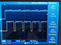
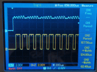
Here you go, this is with Ch1 on IC23P9, and Ch2 on IC2P12. Let me know if there's anything else you'd like to see with these steps.

Steps 18:
ezgif-2-a04e206588.gif

Step 19:
ezgif-2-9b00eb1002.gif

I hope to have some more time later this afternoon to review the rest of your post.
 
I would concentrate on IC32 and IC33.

Both ICs should have pin 1 (/CL) HIGH. This comes from the external SYNC input (that should have a shorting link inserted) and via IC36 pins 1 and 2. If we see any low-going pulses here, we are in trouble...
IC32 & 33 pin1 are both high.

IC36 pin 1 is low, my shorting link for SYNC is connected to GND.

IC36 pin 2 is high.

Likewise, both ICs should have pin 2 (CK) fed from our 3.58 MHz clock.
Yes I have 3.59 clock signal on both pin 2's.

The only other common input pin to these ICs is pin 9 (/L). It would be interesting to see what is on this pin with both D5=0 and D5=1.
I have the 16KHz clock on both pin 9's. D5=0/1 doesn't affect these pins
 
After that, we will be looking at the A, B, C and D outputs from ICs 32 and 33.

When the /L pin is LOW, the outputs should be preset to ABCD = 1000.

When the /L pin is HIGH, IC 32 and 33 should count up from the initial value of 1000. The carry from IC 33 should count +1 into IC 32.

One possibility is that /L is prematurely loading IC 32 and IC 33. In this case we have to work our way back in the logic.

The other possibility is a faulty IC32 or IC33.

The other possibility is faulty logic gates that 'merge' the pulses generated from IC32 and IC33.

If it was me, I could see myself using IC32 pin 9 (/L) as a trigger for the oscilloscope and then having a poke around the outputs from IC32/33 and the resultant logic (toggling D5) to see what is going on. The logic gates are quite simple (AND and OR gates) so there should be no problem in looking for inputs that do not work as expected.

I'm not sure if the rest of these test will make sense since pin 9 may not be what we expected.

However, looking at IC32, using I do see A=1, B/C/D=0.

But looking at IC33, A is measuring an odd 1.8V. B/C/D=0. I only have these 2 74161 chips. So I tried swapping them to see if this reading would move to the other chip, but it stays 1.8V on IC33 (pin 3).
 
Hmm,

That is a very odd voltage level.

Can you stick the oscilloscope probe on IC33 A, IC33 B and IC32 A please to see what we have in terms of frequency and high/low voltage.

1.8 V is in the indeterminate area for TTL logic levels.

As both chips do the same thing (when in the IC33 socket) I suspect that a gate it is connected to is dragging the voltage down.

Dave
 
Can you stick the oscilloscope probe on IC33 A, IC33 B and IC32 A please to see what we have in terms of frequency and high/low voltage.

There is no pulse on these pins just a constant voltage

33 A (p3) = 1.8V
33 B (p4) = low

32 A (p3) = high
 
Are you measuring the A input or A output?

I am meaning the output...

However, the A input should be hard-wired to +5V - so it shouldn't be anything less than 4.8V...

Dave
 
Ok now I'm seeing pulses there

33 A (p14) = 1.79 MHz
33 B (p13) = ~896 KHz

32 A (p14) = ~111 KHz

Check that pin 3 of both IC32 and IC33 has a PCB track to +5V though.
Are you saying pin 3 should be tied high? I do not see that on the foils or the PCB.
 
I can see it on the red/blue foils in the manual (just).

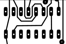
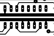
IC33 pin 3 is connected to pin 7 which is connected to pin 10 which is then connected to the nearby +5V rail.

IC33 pin 10 should have a PCB track on both the red and blue sides (i.e. both sides) of the PCB.

Check the voltage readings on IC33 pins 7 and 10 as well. We may be missing a short segment of PCB track?

Dave
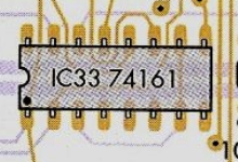
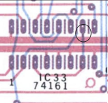
I do not see that on Hugo's drawings for pin 10 or on this foil - am I looking at the wrong thing?
1711396155849.png

I guess I do see a small trace going from pin 10 back to the +5V rail here which is I think what you're seeing:
1711396481492.png

However I don't see that trace on Hugo's drawings either:

Top:
1711396637586.png

Bottom:
1711396597660.png

Should I just try jumpering it & see what happens?
 
This little PCB track appears to be missing - hence the strange voltage. It is due to the internal 'weak pull-ups' within IC33 itself.

However, normally, an unconnected input to a TTL device will read as a logic '1'. So, in this case, it will probably work by accident rather than design.

The IC33 pin that you have circled has a darker 'blue' than the other 'blue' tracks and track segments - indicating to me that there is a red track overlaying it that has got missed.

HOWEVER, I would not 'short it out' until a few other people have had a look and voiced their opinions. Shorting something to the +5V rail is quite drastic. Myself, I would probably pull it to +5V using a 1k resistor.

I still don't think that this will fix your problem - but there could be other tracks like this (especially if they should be pulled down to 0V where (if the track is missing) they will float high and 'misbehave')!

Dave
 
Back
Top