Ah, to clarify, I didn't mean I had all those part numbers. I do see that was confusing. What I meant was: someone earlier had posted a digitized version of the PC-8001 "manual" (thank you!) which seemed to be from the UK ("B") variant (which is fine). I had trouble finding part numbers for things I was looking for, so I having the part numbers typed out in text I think would help with some searches in the future.
Ah! Well, excepting the disk units, I wouldn't count on finding those parts easily, and even if you do chance across them, they are likely to be very expensive. Sadly, they're mostly quite rare now. Note that you can use newer drive units (such as the PC-80S31) with the PC-8001 as well. You'll still need a PC-8033, but you can actually build one of these yourself fairly easily as it's a pretty simple device (just an 8255 PPI and a bit of decoding logic). Plans are available, though I don't have any to hand right now.
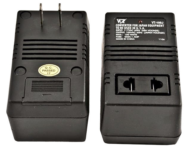
Perhaps for the purposes of saving/loading from the tape, maybe the 100V down convert is necessary to keep the proper timing/speed of the data recording?
Nope. All timing is run from the crystal-controlled computer clock, so even a different voltage on the motherboard wouldn't affect this. But:
But from my own CPU overclocking days, yeah cranking up the voltage 10-20% was necessary, but at a cost of heat....
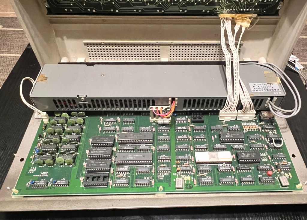
That was and is different in that it's actually changing the voltage delivered to the CPU, which is not the case when you use 120 VAC to power a PC-8001. As with most computers of that era, a transformer converts the input AC to DC voltages somewhat above the voltages the board needs. These are then run through a
linear regulator which takes a variable DC input voltage and produces a fixed output voltage, dissipating the extra energy as heat, so the voltage on the motherboard never changes (unless you don't feed enough voltage into the regulator). A typical input would be 8 V for a 5 V regulator, so if you connect a PSU designed for 100 VAC to a 120 VAC line, that 5 V regulator input will then rise to about 9.5 V. This is still
well within the specs of the regulator (which can handle up to at least 15 V), so long as the regulator can dissipate the heat. The heat dissipation margins should easily handle the extra generated by only a 20% input voltage rise.
Specifically from that manual, yes it seems I'd like to find (or build) a PC-8062 RS-232 Cable. Then that level is always confusing: on the 1980 CoCo, I measured its RS-232 operating at -12V to +12V. Was it RS-232C that did the revision of the spec to be -5V to +5V ?
RS-232 is almost invariably run at ±12 V, though technically the spec allows anything from ±3 V to ±15 V. But the PC-8001 onboard serial is what's referred to as "TTL serial": 0V and 5 V instead of -12 V and +12 V. This needs to be converted if you want to use it with RS-232 devices. There are plenty of chips and adapters to do that conversion, but you may not need it: if you're e.g. connecting to a USB serial interface you can simply buy one that also does TTL levels (i.e., also doesn't have the conversion to ±12 V) and directly connect the PC-8001.
Aside from finding the edge connector adapter, is there a wiring diagram for the PC-8062 cable?
Yes, in the
same document to which I already gave you a link. (There's lots of other useful information in there as well, and yet more in other files in that directory. All these files also include links to further information and references.)
")