• Please review our updated Terms and Rules here

NeXT DSP memory

NeXT

Veteran Member
Joined
Oct 22, 2008
Messages
8,149
Location
Kamloops, BC, Canada
Both the NeXT Cube and the Stations had the ability to be upgraded with additional memory for the DSP. The problem was however that not many people bought the upgrade and now quite a few people want a stick.

I have heard of other kinds of SIMMS being reverse-engineered and it would be wonderful if a stick of DSP memory could be reverse- engineered as well. There was a thread on it on another forum however the project stalled, being short just figuring out what was hidden in the center layer of the SIMM.

The thread being mentioned here and with yours truly being the one who made the transparent trace drawings and cleaning up of the SIMMS that were pictured.

DSP-Top-P.png

DSP-Bottom-P.png

DSP-Top-2.png

DSP-Bottom-2.png

DSP-layers.png

DSP-Top-P-d.png


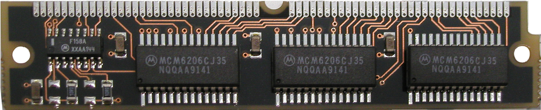
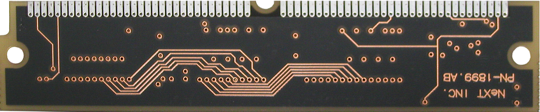
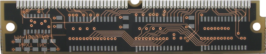
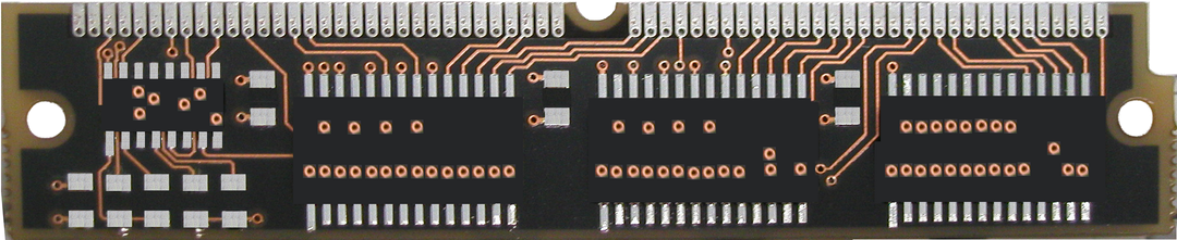
The components should not be an issue to find however we just need to finish Reverse-engineering the traces before I can go and send off the transparencies off to the shop to make the PCBs.

Does anyone want to lend a hand?
 
Hand

Hand

Is that a quad-layer board ?
How was the second pic from the bottom generated ? (The one with the crossing traces )
My Cube is sitting in storage. I'd be more than happy to offer up some time, but I might need some guidance. PM, anyone ?

patscc
 
Hi
All the parts are standard parts. Can't one just get the connector
pinouts and chip pinouts.
There is nothing magic in the wiring of a SIMM. Things like wiring
A0 to A0 and D1 to D1 are not that complicated. The decoder chip
seems to be a 'F158.
Dwight
 
Simm

Simm

SIMM's come in a wide variety of shapes and sizes, and mappings to boot.
(30 pin, 64 pin, 68 pin, 72 pin) and these are just the "pins", not even the mappings of pin to function.
I gotta say, the DSP SIMM does kinda look like the Mac IIfx's expansion memory, although I don't know if the IIfx takes static.
Just the fact the the DSP stick takes static makes it a bit of a freak, since most SIMMS are populated by dram.

Dwight Elvey said...connector pinouts
As Dwight Elvey said, with that, it'd be a lot easier, and might even make one want to update the design with more current ( and hopefully increased availability ) parts.
patscc
 
Is that a quad-layer board ?
How was the second pic from the bottom generated ? (The one with the crossing traces )

That was me messing in photoshop. It just shows where the top and bottom layer traces go.

As for pinouts on the chips as well as for the SIMM slot itself I have them stored away as well as they are on that website I linked to above.
 
You should download the EAGLE program for designing circuit boards. From it you can do the layout of the traces and the chips then upload it to www.batchpcb.com to have some custom boards made.

It costs $2.50 per square inch plus a per order processing fee of $10 to have custom boards made. Once you get the working SIMM board you can order a couple of dozen boards and sell them.

RJ
 
I already have the Eagle schematic software (as well as an older DOS-based schematic program) and I'm working on moving my work to that however I can't send anything off to batchpcb until I finish off the center layer. That is where I need your help as my knowledge with electronics does not really extend into this area.
 
I already have the Eagle schematic software (as well as an older DOS-based schematic program) and I'm working on moving my work to that however I can't send anything off to batchpcb until I finish off the center layer. That is where I need your help as my knowledge with electronics does not really extend into this area.

Use a digital multimeter to pin out the traces. I doubt the center layer is anything more than a ground plane to keep EMI/RFI down.

Raymond
 
I don't actually own the stick. In fact, we con only confirm that at least two people have one and neither are close enough for me to drop by and give it the one over with a multimeter.
If we are to do this we can either A: look for someone else who is willing to mail me the stick and let me analyze it and mail it back or we look at the components on (and off) the stick and try and figure out what trace goes where.
 
stickless in Canada

stickless in Canada

NeXT said...I don't actually own the stick
Ah.
I can run over to my storage unit tomorrow and grab my cube and see if I've got one (can't remember if I do or not ) if someone tells me where to look.
patscc
 
the SIMM sticks out like a sore thumb on the board. Just look for the White SIMM slot and anything plugged into it.

dsp-sram-simm.jpg
 
Well, having reverse engineered a number of items in the past, and, if anyone is interested, the first thing I would do is hold the SIMM up to a high intensity lamp and see if you can find traces through the shadow mask. If so, then I would unsolder the chips and draw the circuit freehand and then plug it into Eagle and reproduce it.
If not, well, then there is a problem as, even if you had the chip pinouts, there is nothing to say they don't do something fancy in that middle layer.
One thing to remember is that, even if you trace the runs (and I'd use a curve tracer as opposed to an ohmmeter), you have to remember to check every pin on the circuit to every other pin to see if they are tying anything together.
 
Curve Tracer

Curve Tracer

Druid6900 said...curve tracer
Unfortunately, if you're talking about a voltage/current type curve tracer, I don't have one. I could rig one up with a scope, I guess, but why ? With a multimeter I can keep the voltage nice & low so I don't have to worry about misinterpreting a conducting junction triggered by to high a voltage, or frying a gate.

On the rare occasion I've had to do this (admittedly tedious ) kind of task, a good multimeter seems to work ok.
I am interested though, what would one gain by using a stand-alone curve tracer, or one rigged with a scope ?

patscc

Well, for one thing, I can tell if the pin branches off to a passive component by the shape of the curve and then go looking for that passive component.

The curve tracers that I've built have a high/low setting to avoid just the problems you've mentioned.
 
tracer & passive

tracer & passive

Druid6900 said...off to a passive component
Ah, that makes sense. In the context of the SIMM, while it does a few caps & resistors, I didn't occur to me that that would be a problem. I can definately see the advantage on larger,denser boards.
Druid6900 said...The curve tracers that I've built
Neat. Are they scope-based ?

patscc
 
Ah, that makes sense. In the context of the SIMM, while it does a few caps & resistors, I didn't occur to me that that would be a problem. I can definately see the advantage on larger,denser boards.

Neat. Are they scope-based ?

patscc

Yes, they are and I run them on a parallel port driven dual trace digital scope board.
 
Back
Top