track18
Experienced Member
Hi there,
recently my CBM 3032, which used to work fine previously, all over sudden ceased to function and started exhibiting the dreaded "garbled screen" symptom... I was quite sad when this happened since I have so many happy memories about this kind of machine -- after all, it was the second computer type (and the first one featuring a CRT and an alphanumeric keyboard) I learned working with back during my school days.
However, reading about several PET ressurections described in this forum raised my hope that also this baby might get revived to its fullest. Alas, though knowing some *very* basics about electronics and digital circuitry, I definitely will depend on the advice of people being more educated in this kind of matter.
So, here's what I've found out so far:
- Powering on: Screen filled with garbled characters.
- Switching off and back on very quickly (approx. < 0.5 s): garbled characters, then (after 1 s or so) blank screen. It seems that in this scenario the boot sequence at least passes the "clear screen" routine. So the $F000 ROM seems principally ok, since this is where the CPU fetches the RESET vector from ($FFFC/$FFFD), and it seems to point to something reasonable. The "clear screen" routine itself seems to be located in the $E000 ROM -- at least this is where I found something that looked pretty much like some code for filling the video RAM ($8000 - $83E7) with space character screen code ($20) when I scanned the corresponding VICE emulator ROM image for the LDA #32 byte sequence (A9 20):
So one might assume that the $E000 ROM is also in good shape. No assumptions can yet be made about the other two ROMs, though.
- Re-seating the ROMs didn't improve the PET's condition; so far I haven't dared to re-seat the CPU and the I/O chips since I am not too dexterous when it comes to pulling DIPs out of sockets without bending the pins... Unfortunately neither the video, nor the "normal" RAMs are socketed.
- I purchased a logic probe and had a look at the voltage levels at all the CPU's pins. During a normal powering on, I get the following
The letter codes next to the pin numbers describe the sequence of observed signals during start-up. The first letter stands for the first second after power-on, the second letter for the second second (<= no typo ;-), and the last letter tells the signal level which then lasts on. L and H stand for 'low' and 'high', respectively, and 'P' means 'pulsating', i.e. the probe continuously detects L/H transitions. '?' just means that different address and data lines exhibit very different behaviour during the first second; some of them give a H, some a L, and some others something inbetween.
Remark: According to the clock pins (PhX), there is a continuous heartbeat. However, the SYN pin stops emitting pulses after the second second, indicating that the CPU ceased to execute commands. This is in accorance with the observation that both the address and the data bus stop talking to the system at the same time point.
Remark: The last thing the CPU did before halting seems to read (R/W' is H) %11100110 = $E6 from address $FFFF. That's in so far very nice since this is exactly the value that should reside at this address according to the VICE ROM image (and which is the hi-byte of the IRQ vector $E61B). However, what puzzles me is that the IRQ line remains high all the time -- shouldn't there be like 60 incomming interrupt requests per second?
- Since switching the power on and off too often too quickly is supposed to be unhealthy for the CRT circuitry, I decided to install a reset button which would connect GND (from pin 1 of the user port) to capacitor C68 of the power-up reset circuit (well, that's what I was told). The thingy works fine, I see CPU's RES line going L for about one second when pushing the button, and I get the blank "powering off and on quickly" screen.
Here's the what I normally find at the CPU after doing such a reset:
Remark: According to the activity found on the R/W', address and data lines, the CPU *does* do something. The question remains: what? And again there seem to be no interrupt requests -- the IRQ line remains constantly either H or L.
Remark: Occasionally, after hitting reset the CPU seems to get stuck in a state in which it doesn't talk on to the bus anymore. I missed the opportunity to check all data and address lines, but I suspect it might be the same jam state the CPU's gets stuck in after a cold power-on.
- Months ago I connected a small audio amplifyer to the user port M pin (CB2) for audio output. When pulling up the volume, I hear some interference from the PET's motherboard as a humming or hissing sound of different tones. For instance, after powering on, I first hear the typical 50 Hz of our national AC grid, during the second second there's a kind of beep, and afterwards it's the 50 Hz humming again. When hitting reset, after a second I frequently also hear the beeping "power-on" sound, followed by a lasting hissing which I suppose to be generated by the CPU busily accessing the bus. (Sometimes, however, there's barely any sound other than the 50 Hz, even though the bus lines are busy.) Funny enough, I do not always get the "power-on beep" during reset; sometimes I get a more noisy sound, sometimes just a clicking noise.
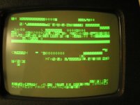
- *Very* occasionally (I thing it has happened only twice or thrice) I get another funny screen after quickly re-powering the PET or after hitting reset. It is mainly blank and shows some intermittent lines of garbage, including the words "IGNORED" and "REDO FROM START". Don't remember to ever have them encountered during my school days, though... ;-) [Don't know yet how to show images in-line, but I attached a "screen shot".]
So - for any hints where to go next I'd be really grateful...
recently my CBM 3032, which used to work fine previously, all over sudden ceased to function and started exhibiting the dreaded "garbled screen" symptom... I was quite sad when this happened since I have so many happy memories about this kind of machine -- after all, it was the second computer type (and the first one featuring a CRT and an alphanumeric keyboard) I learned working with back during my school days.
However, reading about several PET ressurections described in this forum raised my hope that also this baby might get revived to its fullest. Alas, though knowing some *very* basics about electronics and digital circuitry, I definitely will depend on the advice of people being more educated in this kind of matter.
So, here's what I've found out so far:
- Powering on: Screen filled with garbled characters.
- Switching off and back on very quickly (approx. < 0.5 s): garbled characters, then (after 1 s or so) blank screen. It seems that in this scenario the boot sequence at least passes the "clear screen" routine. So the $F000 ROM seems principally ok, since this is where the CPU fetches the RESET vector from ($FFFC/$FFFD), and it seems to point to something reasonable. The "clear screen" routine itself seems to be located in the $E000 ROM -- at least this is where I found something that looked pretty much like some code for filling the video RAM ($8000 - $83E7) with space character screen code ($20) when I scanned the corresponding VICE emulator ROM image for the LDA #32 byte sequence (A9 20):
Code:
e246   A9 20      LDA #$20
e248   9D 00 80   STA $8000,X
e24b   9D 00 81   STA $8100,X
e24e   9D 00 82   STA $8200,X
e251   9D 00 83   STA $8300,X
e254   CA         DEX
e255   D0 F1      BNE $E248
So one might assume that the $E000 ROM is also in good shape. No assumptions can yet be made about the other two ROMs, though.
- Re-seating the ROMs didn't improve the PET's condition; so far I haven't dared to re-seat the CPU and the I/O chips since I am not too dexterous when it comes to pulling DIPs out of sockets without bending the pins... Unfortunately neither the video, nor the "normal" RAMs are socketed.
- I purchased a logic probe and had a look at the voltage levels at all the CPU's pins. During a normal powering on, I get the following
Code:
     Pin         Pin
VSS  21 L    ?PH 20 A11
A12  22 ?PH  ?PH 19 A10
A13  23 ?PH  ?PH 18 A9
A14  24 ?PH  ?PH 17 A8
A15  25 ?PH  ?PH 16 A7
D7   26 ?PH  ?PH 15 A6
D6   27 ?PH  ?PH 14 A5
D5   28 ?PH  ?PH 13 A4
D4   29 ?PL  ?PH 12 A3
D3   30 ?PL  ?PH 11 A2
D2   31 ?PH  ?PH 10 A1
D1   32 ?PH  ?PH 09 A0
D0   33 ?PL  H   08 VCC
R/W' 34 HPH  LPL 07 SYN
N.C. 35 -    H   06 NMI'
N.C. 36 -    -   05 N.C
Ph0  37 P    H   04 IRQ'
SOV  38 H    P   03 Ph1
Ph2  39 P    H   02 RDY
RES' 40 LH   L   01 VSS
The letter codes next to the pin numbers describe the sequence of observed signals during start-up. The first letter stands for the first second after power-on, the second letter for the second second (<= no typo ;-), and the last letter tells the signal level which then lasts on. L and H stand for 'low' and 'high', respectively, and 'P' means 'pulsating', i.e. the probe continuously detects L/H transitions. '?' just means that different address and data lines exhibit very different behaviour during the first second; some of them give a H, some a L, and some others something inbetween.
Remark: According to the clock pins (PhX), there is a continuous heartbeat. However, the SYN pin stops emitting pulses after the second second, indicating that the CPU ceased to execute commands. This is in accorance with the observation that both the address and the data bus stop talking to the system at the same time point.
Remark: The last thing the CPU did before halting seems to read (R/W' is H) %11100110 = $E6 from address $FFFF. That's in so far very nice since this is exactly the value that should reside at this address according to the VICE ROM image (and which is the hi-byte of the IRQ vector $E61B). However, what puzzles me is that the IRQ line remains high all the time -- shouldn't there be like 60 incomming interrupt requests per second?
- Since switching the power on and off too often too quickly is supposed to be unhealthy for the CRT circuitry, I decided to install a reset button which would connect GND (from pin 1 of the user port) to capacitor C68 of the power-up reset circuit (well, that's what I was told). The thingy works fine, I see CPU's RES line going L for about one second when pushing the button, and I get the blank "powering off and on quickly" screen.
Here's the what I normally find at the CPU after doing such a reset:
Code:
     Pin         Pin
VSS  21 L    P   20 A11
A12  22 P    P   19 A10
A13  23 P    P   18 A9
A14  24 P    P   17 A8
A15  25 P    P   16 A7
D7   26 P    P   15 A6
D6   27 P    P   14 A5
D5   28 P    P   13 A4
D4   29 P    P   12 A3
D3   30 P    P   11 A2
D2   31 P    P   10 A1
D1   32 P    P   09 A0
D0   33 P    H   08 VCC
R/W' 34 HP   P   07 SYNC
N.C. 35 -    H   06 NMI'
N.C. 36 -    -   05 N.C
Ph0  37 P    ?   04 IRQ'
SOV  38 H    P   03 Ph1
Ph2  39 P    H   02 RDY
RES' 40 LH   L   01 VSS
Remark: According to the activity found on the R/W', address and data lines, the CPU *does* do something. The question remains: what? And again there seem to be no interrupt requests -- the IRQ line remains constantly either H or L.
Remark: Occasionally, after hitting reset the CPU seems to get stuck in a state in which it doesn't talk on to the bus anymore. I missed the opportunity to check all data and address lines, but I suspect it might be the same jam state the CPU's gets stuck in after a cold power-on.
- Months ago I connected a small audio amplifyer to the user port M pin (CB2) for audio output. When pulling up the volume, I hear some interference from the PET's motherboard as a humming or hissing sound of different tones. For instance, after powering on, I first hear the typical 50 Hz of our national AC grid, during the second second there's a kind of beep, and afterwards it's the 50 Hz humming again. When hitting reset, after a second I frequently also hear the beeping "power-on" sound, followed by a lasting hissing which I suppose to be generated by the CPU busily accessing the bus. (Sometimes, however, there's barely any sound other than the 50 Hz, even though the bus lines are busy.) Funny enough, I do not always get the "power-on beep" during reset; sometimes I get a more noisy sound, sometimes just a clicking noise.
- *Very* occasionally (I thing it has happened only twice or thrice) I get another funny screen after quickly re-powering the PET or after hitting reset. It is mainly blank and shows some intermittent lines of garbage, including the words "IGNORED" and "REDO FROM START". Don't remember to ever have them encountered during my school days, though... ;-) [Don't know yet how to show images in-line, but I attached a "screen shot".]
So - for any hints where to go next I'd be really grateful...
")