Hi everyone,
finally some pieces fell into place... Here's what I found over the last few days:
Clock Signal
============
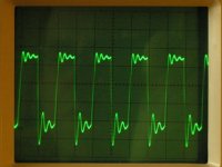
Can't help ya with your problem, but those traces look suspiciously like a mis-adjusted probe (or low-bandwidth scope); are you using a high-impedance (x10) probe and is it properly compensated?
The photos I posted do indeed show measurements done with the probe set to 1x, but repeating the tests with the x10 setting (after proper compensation, of course ;-) ) gives very similar results, i.e. again with damped oscillations riding on the pulses.
CPU and VIA Replacement
=======================
I dared swapping the PET's CPU and VIA with their counterparts from a working 1541 disk drive (one at a time). The drive was still working with either of the PET chips, and the PET was still misbehaving with the drive's ICs. I take this as an evidence that the PET's CPU and VIA are, in principle, ok.
Halting the CPU
===============
I used GND (from the internal cassette port) to drag the CPU's READY line to L (accessed at pin 23 of J4), as discussed in previous postings. Most of the time I found $FFFF on the address bus, sometimes something weird like $90FF or $AAFF, and frequently something in the $E6xx range, in particular $E61E, $E620, $E621, $E624... and sometimes $E6FF. Apart from the latter, these addresses lay within the IRQ handler, which starts at $E61B and looks like
Code:
.C:e61b   48         PHA         ; save A, X and Y on stack
.C:e61c   8A         TXA
.C:e61d   48         PHA
.C:e61e   98         TYA
.C:e61f   48         PHA
.C:e620   BA         TSX         ; get stack pointer
.C:e621   BD 04 01   LDA $0104,X ; get status register from stack
.C:e624   29 10      AND #$10    ; check for break flag
.C:e626   F0 03      BEQ $E62B   ; no break: skip next instruction
.C:e628   6C 92 00   JMP ($0092) ;   handle BRK
.C:e62b   6C 90 00   JMP ($0090) ; handle hardware interrupt
$90/$91 contains the hardware IRQ vector ($E62E), while $92/$93 points to the BRK handler, which resides at $FD17. I'll come back to this later.
One thing, however, that disturbs me (sensu definition #2 ;-) ) is that the CPU didn't resume its work after releasing READY from GND -- only a reset could persuade it do something again.
ROM Test
========
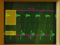
As announced earlier, I plugged the ROM chips into my breadboard, wired them to provide power and appropriate chip select signals (as shown below)
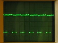
and manually applied various values to their address lines in order to read out the contents of the corresponding memory locations. Here are images of me reading out bits 5 (L) and 6 (H) of address $C000 (which contains $40):
For each ROM, I sampled at least the addresses $x000, $x001, $x002, $x003, $x004, $x008, $x010, $x020, $x040, $x080, $x100, $x200, $x400, and $x800 and compared the readouts with the VICE ROM images.
The $C000, $D000 and $E000 ROMs turned out fine -- but when reading out the first few bytes of the $F000 ROM I only got zeros -- where I should actually find some PETSCII-coded error messages! I continued taking some more samples than for the other ROMs, and a pattern seemed to emerge (values in brackets indicate the contents of the corresponding VICE ROM image address):
Code:
$F000: 00 (54)
$F001: 00 (4f)
$F002: 00 (4f)
$F003: 00 (20)
$F004: 00 (4d)
$F005: 00 (41)
$F006: 00 (4e)
$F007: 00 (59)
$F008: 20 (20)
$F009: 46
$F00A: 49
$F00B: 4C
$F00C: 45
$F00D: D3
$F00E: 46
$F00F: 49
$F010: 00 (4c)
$F011: 00 (45)
$F018: 49
$F019: 4C
$F020: 00 (4f)
$F021: 00 (50)
$F028: 20
$F029: 4E
$F040: 00 (a0)
$F048: 50
$F080: 56 (52)
$F081: 4F
$F088: 54
$F100: 00 (8d)
$F108: A9
$F180: DF (5F)
$F181: F2 (D0)
$F200: 00
$F208: D0
$F400: 00
$F408: 90
$F800: 00
$F808: F6
I got a $00 in all cases where A3 was L, except for $F080 and $F180 -- here I got non-zero, though equally wrong values. So this ROM seems heavily corrupted!
I also tried to figure out how exactly my ROM's false values should theoretically affect the boot process and if this was compatible with my PET's symptoms. So first for the relevant vectors:
Code:
$FFFC: D1
$FFFD: FC
$FFFE: 1B
$FFFF: E6
Apparently, the RESET ($FFFC/$FFFD => $FCD1) and IRQ ($FFFE/$FFFF => $E61B) vector bytes still were what they ought to be. However, wenn following the RESET vector to its target address, I realized that I did not only get loads of false values, but these values occasionally also changed over time! More precisely, immediately after turning on power, I frequently got values with many bytes set (like $FF, $FB etc.), and during the next 30 or so seconds more and more bits turned L, sometimes, but not always, until the values actually exptected were reached. For instance, for the first seven addresses I found values like
Code:
$FCD1: FE/FB/B6 (A2)
$FCD2: FF       (FF)
$FCD3: FA/9A    (9A)
$FCD4: F9       (D8)
$FCD5: 78/20    (20)
$FCD6: FE/DE    (DE)
$FCD7: FD/E1    (E1)
Now sooner or later one of the false values almost certainly must lead to a CPU jam (=> no activity on the data/address bus and R/W, which is what I encounter immediately after turning on the computer) or a BRK instruction ($00), which will cause a software interrupt.
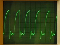
Now let's again have a closer look at the interrupt routine, which lives in one of the "good" ROMs (at $E61B). Since we came from a BRK, it will try to branch to the BRK handler, which is at $FD17 in the bad ROM. Reading out this addres yields -- tataa! -- another false value, namely $00. Consequently, any initial BRK will cause an infinite number of follow-up BRKs -- and this is most likely what I observe as recurring pattern in the R/W signal:
The first, somewhat longer dip, probably corresponds to the BRK instruction itself, which writes the 2 byte program counter and the processor status to the stack, and the subsequent three smaller dips are caused by the three PHA instructions at the start of the interrupt handler.
What next?
==========
Now having most likely identified a major problem with my PET, the question ist: where to get a new $F000 ROM from? Well, the supermarked next door doesn't have them on stock -- but I could perfectly live with a surrogate like a non-original, modern-type EPROM containing the original code. From the
http://vintage-computer.com/vcforum/showthread.php?t=14984 thread I've learned that some of you guys are quite competent regarding EPROMs -- do you know some nice introductory web resources where one could learn something about EPROM types and programming in general and with regard to substituting damaged vintage ROMs?
Happy easter (if you happen to celebrate this holiday)! --
")