• Please review our updated Terms and Rules here

Looking for a special LED

Lutiana

Administrator
Staff member
Joined
Mar 26, 2009
Messages
3,302
Location
Dublin, CA USA
A few years back I remember coming across an LED that changed color based on the voltage it was fed. I have no idea what this type of LED was called but I need a few of them.

The max voltage I will feed to them is 9v, and I want to use them as an indicator of battery level (ie as my 9v battery drains, the LED changes color and eventually turns off).

Any ideas on where I can get such a beast?
 
I haven't seen those, but I once built a similar type of battery tester using several leds and different zeners. It was a crude design but it is simple to implement and gives a very realistic (practical) indication.
 
If you use a standard green led and no current-limiting resistor, as you increase the voltage across it, it eventually starts to glow red, then goes out. This only works once though ;)
 
If you use a standard green led and no current-limiting resistor, as you increase the voltage across it, it eventually starts to glow red, then goes out. This only works once though ;)

Nice! I'll keep that in mind :D

Actually I am trying to go the other way. Basically the LED changes color as the 9v battery runs down.

I know I had an LED like this at one point, but I can't even remember what it was called.

Edit: Here is a video of what I am talking about. I'd want one that goes up to 9V though.
 
Last edited:
Is there a simply way to turn on an LED when the voltage drops below a certain point?

Ie, a RED led lights up when the battery drops below 2v?
 
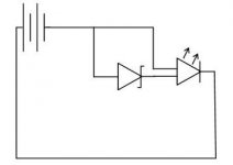
So if I am understanding this correctly, the attached circuit will show 1 color till the voltage drops to a certain point and then it will switch colors.

Am I correct?

attachment.php
 

Attachments

  • zener.jpg
    zener.jpg
    6.8 KB · Views: 1
Reverse the zener--you want the reverse breakdown characteristic--and add a current-limiting resistor in series with the cathode of the LED. The value depends upon the brightness of the indicator and the current rating of the LED.

Most common LEDs are rated for 20 ma. full brightness, so the resistor would be about 7 volts/ .020 amp = 350 ohms for a 9v battery (the LED drops about 2 volts). 1K would give you less brightness, but only draw about 7 ma.

So, to summarize--resistor between the negative terminal of the battery and the cathode of the LED. One anode of the LED connected directly to the positive terminal of the battery; the other anode connected to the anode of the zener; the cathode of the zener connected to the positive terminal of the battery.
 
Ok, this gets more complicated.

I am actually using a voltage regulator to drop the voltage to 5v. Now I assume that when the battery drops below 5v the regulator won't step it up, but merely pass it through, is this a correct assumption?

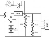
So assuming that I am using a 5.1V zener diode that says it has a trigger voltage of about 1v, does this mean I will actually need a 100ohm resistor ([5 - 2] / .03 = 100, using this LED)? Using the circuit I posted below. Will the LED change color at > 1v?

This is the circuit I am trying to modify with the LED indicator:

attachment.php
 

Attachments

  • USB_charger.jpg
    USB_charger.jpg
    27.8 KB · Views: 1
Last edited:
A 7805 requires a bit of headroom to regulate. So, you'd want the input voltage to be no less than about 6V.

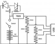
On thinking further we can make this work better. Take the LED cathode and connect it to battery negative (no resistor). Next take a 1K resistor and connect it between one LED anode and the positive battery terminal after the switch.

Take a second 1K resistor and connect it between the positive battery terminal after the switch and the cathode of the zener. The zener anode and LED anode stay connected. This modification (adding a resistor) will minimize the interaction between the two LEDs.

Note that the indicator is on the battery side of the voltage regulator; i.e. between the regulator side of the switch and the negative battery terminal. That way, it will monitor the battery voltage and not the voltage coming out of the regulator.

The value of the zener should be less than 4v. Try a 1N5913, 1N5914 or 1N5915. See which meets your needs the best.

Another approach would be to minimize the draw on the battery by having only one LED on at a time. The circuit gets a bit more complicated, however...
 
I think this is what you meant:

attachment.php


The value of the zener should be less than 4v. Try a 1N5913, 1N5914 or 1N5915. See which meets your needs the best.

Is there a Jameco equivalent? I can't seem to find those exact part numbers. Will this do?

Another approach would be to minimize the draw on the battery by having only one LED on at a time. The circuit gets a bit more complicated, however...

I am not all that concerned with the draw. Its an emergency charger, and if the LED changes color then its time to swap the battery, so draw does not matter too much.

If I am understanding this correctly the LED will change color (since both anodes will be connected) when the battery drops below 4v. Is that correct?
 

Attachments

  • USB_charger.jpg
    USB_charger.jpg
    27.2 KB · Views: 1
Last edited:
A few years back I remember coming across an LED that changed color based on the voltage it was fed. I have no idea what this type of LED was called but I need a few of them.

The max voltage I will feed to them is 9v, and I want to use them as an indicator of battery level (ie as my 9v battery drains, the LED changes color and eventually turns off).

Any ideas on where I can get such a beast?
Take a look at the literature on this National Semiconductor LM3914 chip. This makes for a number of neat little projects and can be fun to play around with. The document includes schematics for several applications of the chip. You can implement the circuit without delving into the inner workings of the chip, or read about how it works internally to give you some ideas for your own project.

http://www.national.com/ds/LM/LM3914.pdf
 
Is there a Jameco equivalent? I can't seem to find those exact part numbers. Will this do?

Yes, to experiment a bit, get the 3.3, 3.6 and 3.9v diodes.

If I am understanding this correctly the LED will change color (since both anodes will be connected) when the battery drops below 4v. Is that correct?

Actually, about 6V (we need to take the drop across the LED into consideration). 6V is about the limit at which the 7805 can regulate reliably anyway.
 
Take a look at the literature on this National Semiconductor LM3914 chip.

Thats a pretty cool chip, I may have to pick one up and play with it, but its a bit more than I need here.


Actually, about 6V (we need to take the drop across the LED into consideration). 6V is about the limit at which the 7805 can regulate reliably anyway.

That is perfect, it means that the light will change when the device can no longer offer voltage to charge the device in question.
 
Boy, with those LEDs and a 7805 most of your battery power is going into light and heat; you might at least consider a switching regulator (if you even need a regulator at all).

I assume there are provisions in whatever you're charging to prevent reverse current?

Google "low battery indicators" and you might pick up some other ideas...
 
Boy, with those LEDs and a 7805 most of your battery power is going into light and heat; you might at least consider a switching regulator (if you even need a regulator at all).

For the sake of my electronics education, what would a switching regulator do for me that a voltage regulator would not?

I'm not looking for efficiency I guess. This design should do nicely in an emergency.

I just pulled the trigger on the parts. The original circuit was designed to act as an emergency charger for an Ipod or Iphone (but should work on any USB chargeable device). I found it here on Jameco's website.

Since most of my family are running around with I-phones I figure it would make a nice stocking stuffer.
 
Last edited:
Back
Top