• Please review our updated Terms and Rules here

What capacitor to use?

per

Veteran Member
Joined
Jan 21, 2008
Messages
3,052
Location
Western Norway
I am considering to add a capacitor on a bistable mechanical switch in my NEStoXT adapter, but I am unsure what streinght the capacitors should be of.

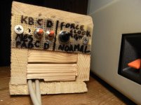
The role of the capacitor is to reduce momentary noise the moment the switch is toggled. The switch is a standard open/close switch, and it "clicks" over quite signifficantly when toggeled.

The input of the switch is connected to ground directly, and the output is connected directly to the input of an open-collector buffer and to +5V through a 10K resistor.

I am considering to use a 0.1uF capacitor, but I am unsure if that it is sufficient.
 
t = RC, so 1E5 ohms * 1E-7F = 1E-2 seconds or 10 msec. Should be adequate unless you've got a very noisy switch.

With the addition of a resistor and a diode, however, you can do better.
 
As Chuck suggested, a proper debounce circuit would be better...but that link points to some site in Russian that doesn't appear to have to do with electronics.
 
t = RC, so 1E5 ohms * 1E-7F = 1E-2 seconds or 10 msec. Should be adequate unless you've got a very noisy switch.

With the addition of a resistor and a diode, however, you can do better.

Due to soldering the logics as compact as possible on a prototype PCB using an array of 3*1 leads, it curently looks like a spider's nest. This is why I want to keep the part-count as low as possible.
 

Attachments

  • RIMG0221.jpg
    RIMG0221.jpg
    91.8 KB · Views: 1
  • RIMG0300.jpg
    RIMG0300.jpg
    90.2 KB · Views: 1
  • RIMG0220.jpg
    RIMG0220.jpg
    87 KB · Views: 1
  • RIMG0219.jpg
    RIMG0219.jpg
    90.8 KB · Views: 1
  • RIMG0301.jpg
    RIMG0301.jpg
    89 KB · Views: 1
Last edited:
Update:
Uploaded some images in previous post. The big black switch is the one in question.
 
I just realized that I will have to add a schmitt trigger of some sort, something I have huge problems seing where I could fit it, along it's inverter.

I will also have to do some "ninja-maneuvers" with a wire-stripper and a soldering iron in order to route the "sharpened" signal to the correct output. The wire that has to be cut is the one going to somewhere on the PCB from the resistor standing up from the PCB rigth under the switch.

Update:
I'm planning to use a 74LS341 schmitt triggered buffer (noninverted output) for this.
 
Last edited:
For anyone interested in schematics, here they are.

Logic IC's used are:
3x 74LS74 = Flip-Flops
1x 7407 = Open-collector buffer
1x 74LS341 = Schmitt-trigger buffer
 

Attachments

  • Schematics.zip
    18.3 KB · Views: 1
Last edited:
Back
Top