Chuck(G)
25k Member
It could even be the resistor itself. It's not completely unknown for a power resistor to change value.
Excellent point!It could even be the resistor itself. It's not completely unknown for a power resistor to change value.
This could be as simple as the traditional shorted or leaking cap; since everything is more or less working it's not likely to be anything serious like a bad IC etc. and it looks like some non-essential part is just creating a partial short across the V+.
Indeed...Mike,
That makes sense that it is the filter cap especially as the power transistor that Tez measured has so much AC on it (assuming it is part of the regulator which we do not yet know).
I didn't know that troubleshooting in the blind could be so interesting!
Indeed...
At this point I probably would not connect a high-current 12V supply, e.g. his car battery, without a good fast-acting fuse in the circuit; mind you, that is one technique for making shorted tantalums obviously visible ;-)
") .
.
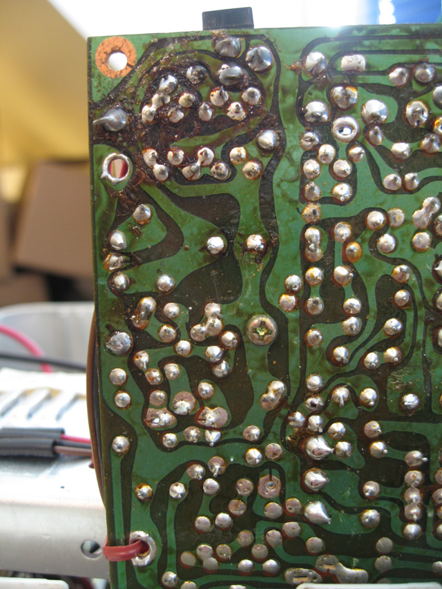
Ok, replaced five electrolytic caps in the near vacinity. No change from that. Also, checked out a single diode just down from the 7W resistor for a short. It was ok.
The ceramic caps among the diodes at the top look in bad shape. Any chance they might be the problem?
Looks like I might need to sketch out a diagram after all. I've never done anything like this so it will be a challenge. Cup of coffee first, then I'll give it a crack.
Tez
). My attempt at circles sucked, so I've represented the two transistors just with a label and three angled lines.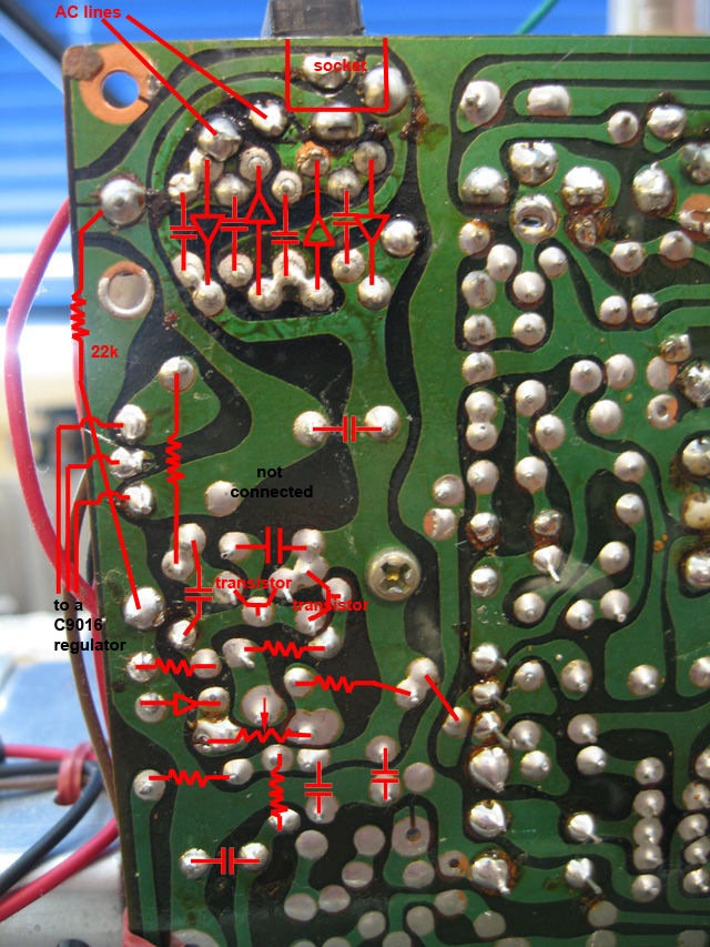

It does, doesn't it... maybe a problem in the video amp, driving too hard and pulling down the +V at the same time?To my eye, it looks like the CRT is being overdriven. Most likely, there's some adjustment pot somewhere that can relieve this or at least improve it. Without any idea of what you're working with, however, it's pretty difficult to say what that might be.
It does, doesn't it... maybe a problem in the video amp, driving too hard and pulling down the +V at the same time?