• Please review our updated Terms and Rules here

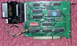
XT IDE Ordering interest? (Was: Xt-ide

XT IDE Ordering interest? (Was: Xt-ide

  • 1

    Votes: 59 52.7%
  • 2

    Votes: 38 33.9%
  • 3

    Votes: 8 7.1%
  • 4

    Votes: 5 4.5%
  • 5+ (please post how many below)

    Votes: 2 1.8%

  • Total voters
    112
Forgive me if I have missed this if the question had been asked before, but:

Has there been thoughts of a hard-card type form factor for these? It would be really cool if I could mount my laptop harddrive that I use on my XT-IDE right on the board instead of a weird place inbetween the floppies.

http://www.downloads.reactivemicro.com/Public/Apple II Items/Hardware/ZIP_DRIVE/Pics/Zip2.jpg (of course, just mounting holes for both desktop size and laptop size in this case).
 
I've got 2 unused bare Rev.01 boards I'd sell & ship for what I paid, $14 each shipped it looks like.

Also, I'd trade one for an adapter to use PS2,AT or USB keyboard with my 5150 :D

Hi, I have plenty of the AT2XTKBD PCBs left if you want some. They are $5 each plus shipping.

Thanks and have a nice day!

Andrew Lynch
 
Forgive me if I have missed this if the question had been asked before, but:

Has there been thoughts of a hard-card type form factor for these? It would be really cool if I could mount my laptop harddrive that I use on my XT-IDE right on the board instead of a weird place inbetween the floppies.

xtidemod-flash.jpg


That's my XT-IDE with 128 MB industrial Flash module...low power, no moving parts, and a truer IDE emualtion than CF cards. Also, 2 million rewrites minimum. I did a write-up on modifying the XT-IDE to provide power on IDE pin 20 here:

http://glitchwrks.com/vintage/xtideflash.html

If you want a 64 or 128 MB module, PM me, as I have 100+. They are available in capacities up to at least 4 GB in the same form factor. I highly recommend them as IDE disk replacements over CF cards!
 
glitch said:
That's my XT-IDE with 128 MB industrial Flash module...low power, no moving parts, and a truer IDE emualtion than CF cards. Also, 2 million rewrites minimum. I did a write-up on modifying the XT-IDE to provide power on IDE pin 20 here:

What's "truer" about the SSD over modern CF (which now run to silly-fast write speeds)?

I attached a CF-to-IDE adapter and use either a Microdrive (a "real" hard drive) or a CF. I also recommended a +5 header on the V2 PCB, but one can be installed as shown here:

CGXTIDE.jpg

Adding both +12 and +5 power headers to the V2 was discussed, but the potential current draw issues (and having to make provision for wide enough traces) was discarded. You can just as easily provide a power cable for your drive.
 
What's "truer" about the SSD over modern CF (which now run to silly-fast write speeds)?

I'm not entirely sure what's different, but I have a lot (more than 75%) of CF cards that won't work with the XT-IDE board or many of the other old computers I've got.

Chuck, those CF -> IDE adapters, like the one you're using, also support +5 on IDE pin 20 as a power supply. I originally modified my XT-IDE for power on pin 20 for use with one that looks identical to what you have. It of course eliminates the need for external wires.
 
Glitch,

I do notice that CFs rated above about 150x seem to have problems with the CF adapters (I found this out the hard way the past weekend). Oddly, they're fine in my camera and even in an old USB 1.1 CF reader.

Clearly, there's something funny going on. I haven't had time to run the problem down (or even google for it) yet. Hopefully, it's just a matter of the CF adapter and not anything bigger.

"Normal" speed CFs work just fine.
 
Adding both +12 and +5 power headers to the V2 was discussed, but the potential current draw issues (and having to make provision for wide enough traces) was discarded. You can just as easily provide a power cable for your drive.

Hi Chuck, the PCB still has both the VCC & GND connector for CF adapters and the 4 pin drive power supply connector. We added a warning label for limited current capacity and wide traces for temporary start up current capacity. It won't support a massive power consuming IDE drive but should handle most of the recent drives.

Thanks!

Andrew Lynch
 
Why isn't there room for wide enough traces? The v1 PCB looks like someone used an auto-router. With a different placement of ICs and hand routing, you should have swaths of ground pour a mile wide.
 
Why isn't there room for wide enough traces? The v1 PCB looks like someone used an auto-router. With a different placement of ICs and hand routing, you should have swaths of ground pour a mile wide.

Ah, I see someone else shares my hatred of the autorouter! It can be a tedious process, but there's nothing nicer (PCB wise) than a well-done hand routed board. Plus, you often can do things that the autorouter doesn't think of, like switching the gate you're using in a 7400 series IC to make routing cleaner.

I think Mike B. mentioned that the XT-IDE was indeed autorouted on one of his machines...is the V2 board going to be autorouted as well? I could probably hand-route it in an evening or two if anyone is interested in having that done.
 
Glitch, what do you use for your hand-routing? Clearly not mylar, tape and india ink...

Why, dry transfers and an X-ACTO knife, of course!

...not anymore, though. By hand-routing, I meant laying down tracks by hand in (insert CAD package) rather than letting the autorouter try to guess it for you. I've never been happy with even simple autorouted projects. I've previously worked in the mastering EQ business, and all of our boards were hand-routed to keep analog noise down...lots of experience laying out discrete opamps, signal processors and such, which makes hand routing a digital circuit simple in comparison.
 
...not anymore, though. By hand-routing, I meant laying down tracks by hand in (insert CAD package) rather than letting the autorouter try to guess it for you. I've never been happy with even simple autorouted projects. I've previously worked in the mastering EQ business, and all of our boards were hand-routed to keep analog noise down...lots of experience laying out discrete opamps, signal processors and such, which makes hand routing a digital circuit simple in comparison.

Some digital circuits, anyway. Take a look at a modern motherboard with what looks to be quarter-mm trace widths and signal paths laid out to provide precise delays and I don't think I'd want to be the guy with tape and X-acto in hand...
 
I'd imagine the motherboard layout people have specialized (or at least better) autorouters than are available to us hobbyists, though. Even Protel/Altium's autorouter left a lot to be desired, but it would at least impedance match traces for you. Still, for the types of digital circuits I'm working with, I find hand-routing the traces to produce better results than the autorouter. For example:

8085cpu06APR.png


I attempted to let EAGLE autoroute that board, just to see what it would do. Lots of crazy angles and curly-cues, and plenty of unconnected airwires left. The max speed of that design is < 10 MHz, so trace lengths aren't critical as they would be in a modern motherboard.
 
That's a nice layout. Here's a prelim of the variant of the XT-IDE mk.II plus some RAM for a PCjr side car. It does uses a couple PLDs, but they essentially replace a tight collection of 74xx chips which should be of similar layout - only more spread out. But it illustrates how clean the latching logic is when the components are well placed and hand routed (latches/buffers in top right corner). Most of this board uses 24 mil trace widths for open signals, 16 for necking, and 32 for power.

jride_300dpi.png
 
I think I can dig up a light board or two if you really want to give it a go!

I'm not Asian enough. The really good PCB layout people I knew during the 70s all seemed to come from that part of the world.

To complete the picture though, you'd need to work up your schematics and mechanicals by hand. Cue the drafting table, T-square and Blueline machine.

I don't think that many young people today appreciate how much handwork went into early PCB production. Simulation? Logic analyzers? In your dreams! :)
 
Yes, even the most basic schematic/circuit board layout tools available for free today beat my first methods, which literally were rub-on dry transfer traces/pads/DIP footprints, an X-ACTO knife, a special resist marker (later discovered to be a Sharpie, and replaced as such), an old tupperware container and Rat Shack FeCl2! Now I can make prototypes with a laser printer, clothes iron, and EAGLE CAD in about 1/4 the time, and they're likely to work the first time since the layout is captured from the schematic. And when I get the board layout to a point I'm confident will work, I can send it off to DorkBot PDX for $5 per square inch, for 3 copies...I probably paid more for just the copper clad back then!
 
My first PCB was on single-sided stock, laid out with tape and marker using a direct-etch process. All the ICs were 900-series RTL flatpack. The component side and foil side were the same, so there was no drilling. Jumpers were done with #26 enameled magnet wire. That was a long time ago and tools were pretty crude.

Prototyping for me now, unless it's very simple, is wire-wrap. I use 0.060 single-sided FR4 PCB stock and simply drill the holes for the components, slightly relieve the foil side of each hole, punch in my pins and I'm all set to start wiring. I thought about using etched boards, but layout's another step that I don't care to do. It's not completely unknown for me to tear out half a prototype and completely redo it, so traditional printed circuit isn't the best choice. SMT gets put on adapters.
 
Well Chuck, at least yours worked. My boss wanted me to construct a thermal imaging laser from a set of drawings. Parts were ordered, board etched, power applied and shazzam! It worked for about 1 billionth of a second to my best estimate, then promptly fried intself into a puddle on the bench. I was more sucesssful down the line with solid stated power supples. After all, it was a R&D lab.
 
Last edited:
im desperately in need of one of these cards i dont solder myself but id like to get an ide (or cf) card going can i get some help?
 
Back
Top