• Please review our updated Terms and Rules here

Would anyone be interested in repairing a PET2001?

Eudimorphodon:
Thank you so much for the 2k version of the PetTester file. I sure hope to do some tinkering this weekend. I got the file from here.
MikeS:
Thanks for the link. I believe I bought 2 of those when he had some sale on the boards.

Being alway inquisitive on new things, I thought I'd like to experience also what the PETTester does (first hand and on my own PET).

RizThomas
 
As a matter of fact, last Thursday I wrote my very own PET memory test program. While I'm not entirely sure how Eudi's one works (and yes, I disassembled it to have a look), I got the feeling it tests if all available memory is good or bad, not being specific which part of memory has a problem.

My program is self-modifying and relies on the fact that the video RAM $8000 is known good. In PET's that have a problem with this memory, neither my nor Eudi's program would work anyway. If suitable, perhaps several efforts can be combined? The CRTC init would be a nice addition, as well as the better visual display of which chip is at fault.

It should be added that my program yet only has been tested in emulation, so I admit not knowing what the outcome will be on my own PET that has a memory problem. Hopefully I will get to know by tomorrow.
 

Attachments

  • pet-memtest.zip
    852 bytes · Views: 1
The CRTC init would be a nice addition, as well as the better visual display of which chip is at fault.

Anders,
This would be a good thing to add, but how are you to distinguish between a 40 column or 80 column setup if the PET is not booting? Could you try to test ROM or just init always as 40 columns so as not to stress the CRT? I suppose you could have to versions...
-Dave
 
Absolutely, the easy and perhaps best approach would be to have one test ROM for each motherboard revision, or whichever resolution is required.
 
As a matter of fact, last Thursday I wrote my very own PET memory test program. While I'm not entirely sure how Eudi's one works (and yes, I disassembled it to have a look), I got the feeling it tests if all available memory is good or bad, not being specific which part of memory has a problem.

It actually only tests the first 1K. When the test runs a location on the screen directly corresponds to a location in the first 1K page. (So technically I guess you can only see the results for the first 1000 bytes, not a binary K.) My thinking behind that is that should be adequate to tell you if the zero page and the stack are OK. Or to put it another way, if the first 1K works the system *should* be able to get into BASIC barring other problems. (And there are some interesting problems that could prevent it but they're pretty odd edge cases. I sort of found one when working on my PET but the particular case of it it wasn't enough to stop it from getting to the BASIC prompt, it just caused some "interesting" behavior when running further test programs.)

My program is self-modifying and relies on the fact that the video RAM $8000 is known good. In PET's that have a problem with this memory, neither my nor Eudi's program would work anyway.

Mine actually doesn't assume that video RAM is known good. It runs entirely from ROM and CPU registers based on the assumption that every scrap of memory in the system can't be trusted. The "show character set" part of the loop is there so if there is a problem with a stuck bit in video RAM you should be able to determine what it is based on which character you get in place of the correct one.

Basically the ROM as it stands is sort of a next step after a NOP generator. It should be able to make even a pretty darn sick PET do "something" and even if that's just display "changing" instead of "static" garbage looking at the patterns of the garbage can give you some clues. But yeah, it's far from comprehensive in terms of telling you *exactly* what needs love.

If suitable, perhaps several efforts can be combined?

Yeah, I'd be happy to collaborate. On the "wish list" I had for improving mine was to have the ROM test the zero page and the stack area and conditionally jump to an extended suite of tests if it determined there was usable memory. I mostly just haven't had the time to work on it much. (And I've also been having a little fun with the mental arithmetic of figuring out how to execute such a conditional branch with a program that keeps entirely to CPU registers when the 6502 only gives you *three*. It *may* be possible since outside the delay loops I actually don't use "y"...)

Among the "extended tests" one I thought might be useful would be to do some simple checksums of the ROM socket area that the user could compare to a table of known good ROM checksums for various BASIC versions. On systems with open ROM sockets (like the Dynamic Boards and later) the user could stuff the Kernal ROM into one of the other locations and test it along with the others. (My lamest idea along those lines is just add a loop that copies a chunk of bytes from each ROM socket to screen memory so the user can compare the resulting garbage to a known good PET's garbage. That's something that could even be done from a register-only loop.)
 
In any case, both your and my programs display "B" as in bad for all tested memory on my faulty PET. When running my program in emulator set as a 4, 8 or 16K machine, the non-connected parts of memory gets "B" while the actual RAM sections get "G". Since my program claims every single RAM block except the video memory is bad, I start to smell the problem might be elsewhere. I haven't yet got to measuring voltages etc, that will be my next task.
 
Absolutely, the easy and perhaps best approach would be to have one test ROM for each motherboard revision, or whichever resolution is required.

Anders and Eud,
This is the CRTC Init code for the 80 column 8032 BASIC 4 machine. The constants loaded into the 6545 are the 17 decimal bytes starting at $E72A. Some of the comments in the listing are mine and may be incorrect.

Code:
 ; Initialize CRTC -- Patch for BASIC 4 or 80 columns?
E07A iE07A LDA #$2A
E07C       LDX #$E7
E07E       LDY #$0E
E080       BNE $E088

 ; Initialize CRTC --
E082 iE082 LDA #$3C ; is this adress for 40 columns???
E084 LDX #$E7
E086 LDY #$0C
E088 iE088 STA $C7   ; Store address of CRTC constant table at C7 and C8 (low byte, hi byte)
E08A STX $C8
E08C LDA $E84C
E08F AND #$F0
E091 STA $D1 ; Length of Current File Name; Does CRT init temporarily use this location?
E093 TYA
E094 ORA $D1 ; Length of Current File Name???
E096 STA $E84C ; Selects lower case for business or upper case/graphics 
E099 LDY #$11 ; Prepare to store 17 bytes from address E72A into the CRTC registers
E09B iE09B LDA ($C7),Y   ; load next CRTC constant, indexed by Y register
E09D STY $E880 ; Store 6545/6845 CRT Controller Register Number (select the register)
E0A0 STA $E881 ; Store 6545/6845 CRT Controller Register Data (transfer data into register)
E0A3 DEY ; decrement Y
E0A4 BPL $E09B   ; If not finished, branch back to $E09B
E0A6 RTS
 
; - Video Chip Setup Table -- e07a DATA BASIC 4, 80 column?
E72A .byte 31 28 29 0F 27 00 19 20 ;1().'.. 
E732 .byte 00 09 00 00 10 00 00 00 ;........
E73A .byte 00 00 ;..
 
; - Video Chip Setup Table -- e08a DATA for 40 column?
E73C .byte 31 28 29 0F 31 00 19 25 ;1().1..%
E744 .byte 00 07 00 00 10 00 00 00 ;........
E74C .byte 00 ;.
 
I'll have to play with the cross-assembler I'm using and see if I can learn how to generate loadable executables with it. (Apparently it's not hard, just haven't tried yet.) I suppose I could test a CRTC initialization routine on my 4016. I wonder if "bad things" would happen if you loaded an 8032's initialization into a 40 column PET. Obviously it won't display properly since it won't have the additional VRAM, but will it actually break anything?
 
I suppose I could test a CRTC initialization routine on my 4016. I wonder if "bad things" would happen if you loaded an 8032's initialization into a 40 column PET. Obviously it won't display properly since it won't have the additional VRAM, but will it actually break anything?

I would not want to try 6545 constants meant for a 12" CRT on a 9" CRT. Let me know the exact type of PET and screen you have and I will disassemble the E code and obtain the numbers for your machine using the VICE PET emulator.
 
I would not want to try 6545 constants meant for a 12" CRT on a 9" CRT. Let me know the exact type of PET and screen you have and I will disassemble the E code and obtain the numbers for your machine using the VICE PET emulator.

My CRTC 4016 is a 12" model.

(As an aside, I'd love to find the CRTC constants to drive a 9" display. Apparently there was a retrofit-intended ROM for Universal boards installed in 9" cases, but I haven't been able to find an image of it. If I can repair the Universal board in my 8032 but the monitor remains a lost cause I'd have an interest in being able to steal the 12" monitor for the 8032 and be able to use 4016's board as a backup for my 9" 4032 or 2001.)
 
I will disassemble the E code and obtain the numbers for your machine using the VICE PET emulator.

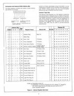
I have looked at some CRTC register data sets and I am puzzled. Register 1 is called Horizontal Displayed and contains the number of displayed characters per line. On a 40 character machine (4016) I see the number 28h which seems correct (40 decimal) but when looking at Model 8032 data I also see the number 28h instead of 50h (80 decimal). I don't know what to make of this yet....

I which I could read back the data in R1 in my 8032 machine, but I think the 6545 does not allow reading its registers.
 
So... I think I recall reading about that anomaly. (The 8032's CRTC programmed as if it's 40 characters wide.) I believe the answer is that the reason it's set up that way is because clocked at 1Mhz an 80 character screen would require too much memory bandwidth to share with the CPU if the CRTC were fetching at a rate corresponding to "a single 8 bit character 80 times a scanline". The way they get around it is the VRAM is actually set up interleaved even/odd so from the CRTC's standpoint it's actually "only" fetching 40 times a scanline, but is displaying a "16 bit wide" character composed of the combined glyphs of two consecutive characters...

Aha, here's the link:

http://6502.org/users/andre/petindex/crtc.html#8032

Weird. Presumably that means when you run one of those 4032 emulator programs on one it sets it up for 20 characters/line?
 
So... I think I recall reading about that anomaly. (The 8032's CRTC programmed as if it's 40 characters wide.)
OK, that makes sense then. Thanks for the link to the CRTC info. I had not seen that before.

Weird. Presumably that means when you run one of those 4032 emulator programs on one it sets it up for 20 characters/line?

Good call! I disassembled enough of the CBM4032 program (converts 80 character screen to a centered 40 character screen so that games display properly) to see that the Register 1 value transferred to the CRTC is indeed 20 decimal.
-Dave
 
I need to spend some time groking the CRTC's manual and try to understand how the other constants work, as I'm sort of wondering now why the 4032 and 8032's settings would necessarily need to vary at all? (My quick reading of the description of the CRTC is that in addition to memory address generation it supplies timing information such as the horizontal and vertical refresh pulses, but it doesn't directly do pixel generation. Does it supply any signals to control the shift registers clocking out the horizontal dots? It would seem if it doesn't then putting the 4032's initialization into an 8032 would probably produce something like a usable screen, although the horizontal width/positioning might be off...)
 
Last edited:
Does it supply any signals to control the shift registers clocking out the horizontal dots? It would seem if it doesn't than putting the 4032's initialization into an 8032 would probably produce something like a usable screen, although the horizontal width/positioning might be off...)

The shift register load and clock (8MHz) are independent of the 6545 so you are probably right about the useable screen. See earlier message 27 for slight differences in register contents between FAT 40 and 80 column. I tried to attach a gif file with register info to this message but it is too small to see so use the link.

Here is a link to a page from a 6545 spec sheet with register info.
 

Attachments

  • 6545_REGS.jpg
    6545_REGS.jpg
    15 KB · Views: 1
Last edited:
Back
Top