• Please review our updated Terms and Rules here

Weaving core memory

IMG_20130330_031039.jpgIMG_20130330_031048.jpgIMG_20130330_031059.jpgIMG_20130330_031115.jpg
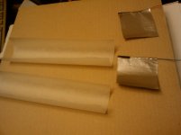
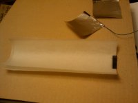
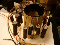
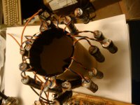
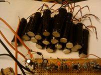
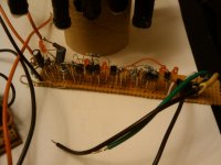
the 4 bit core memory is built on a very old brown pcb at the top of the pic, the larger toroid is the same type as one core memory builder I found online, Wayne used the toroid to build a 1 bit core memory but I thought a smaller core of the same type would work better, I do not know much about toroid core types, but the one used on the site may not be ideal? a smaller toroid should pass the tiny spike with less attenuation, but I will test both.
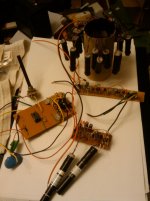
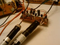
I will only need 3 or 4 wires per core, the 4 bit core was made as a test so I could see if I could thread the cores in the wright shape, also so could electrically test the cores under different conditions so I know its tolerances.
I am getting a microscope for the 0.5mm cores!
 
Last edited:
I also have in the pic a 1.2mm and 0.5mm core with 5 loops of wire threw them 0.17~? in the 1.2mm core and 0.08mm threw the 0.5mm core, this was to test the wire size and if I could do it, when I build a larger core plane,
IMG_20130330_045127.jpgIMG_20130330_045137.jpg
you can hardly see the 0.5mm core on the copper colored magnet wire!
 
prototype

prototype

I did not have any 220pf capacitors for it so I made 3 using baking paper and silver foil, I cant find my capacitance meter, but the circuit worked first time!
 

Attachments

  • IMG_20130329_210029.jpg
    IMG_20130329_210029.jpg
    92.4 KB · Views: 1
  • IMG_20130329_210239.jpg
    IMG_20130329_210239.jpg
    92.3 KB · Views: 1
  • IMG_20130329_210331.jpg
    IMG_20130329_210331.jpg
    89.2 KB · Views: 1
  • IMG_20130329_210446.jpg
    IMG_20130329_210446.jpg
    92.2 KB · Views: 1
  • IMG_20130329_210851.jpg
    IMG_20130329_210851.jpg
    88.3 KB · Views: 1
The top circuit is a counter, the lower circuit is a variable speed 555 timer test board I made out of junk years ago.

when making capacitors it is very important to make shore that the foil plates have any sharp edges that may course damage to the insulator and wrinkles are flatted by running the top or you nail or a tea spoon over it,also its important that the dielectric and foil are pressed firmly together to get a reliable and consistent capacitor, after wrapping the out side with electrical tape I stuff with tissue paper and then epoxy the ends.

wax paper works best, and to avoid any problem with a leaky capacitor its best to have two sheets of wax paper between the sheets of silver foil.
 

Attachments

  • IMG_20130329_211117.jpg
    IMG_20130329_211117.jpg
    93.1 KB · Views: 1
  • IMG_20130329_211134.jpg
    IMG_20130329_211134.jpg
    99.9 KB · Views: 1
  • IMG_20130329_211403.jpg
    IMG_20130329_211403.jpg
    86.8 KB · Views: 1
  • IMG_20130329_211724.jpg
    IMG_20130329_211724.jpg
    88.5 KB · Views: 1
  • IMG_20130330_030747.jpg
    IMG_20130330_030747.jpg
    88.1 KB · Views: 1
Last edited:
I'd like to see some of you guys work out some core logic such as a shift register or a gate. Those (and Parametrons) have been a favorite interest of mine; very different from conventional logic as all operations are performed synchronously with the clock. I've got cores, but not the steady hands or eyes.
 
Last edited:
The thing in my pics that looks like some sort or tree, is the new batch of capacitors with there epoxy hardening, I have made them for the counting circuit, the original circuit I found was for a clock and used 220pf capacitors, but as I want to use it for 0.8mhz to 1.5mhz I think 8.8pf is better, my capacitors are probably under 8.8pf, becos I don't know the dielectric constant of backing paper yet, so I treated it as wax paper, that has a dielectric constant of about 3, but my dad is going to test one capacitor, so I will be able to work out all the other capacitor sizes, if the others capacitors are to small, I made meny more than I can double up with the one on the board, the last pic of them all stacked.
I will need 9 of there capacitors for the counting circuit.
 

Attachments

  • IMG_20130401_212908.jpg
    IMG_20130401_212908.jpg
    85.8 KB · Views: 1
  • IMG_20130401_212928.jpg
    IMG_20130401_212928.jpg
    87.3 KB · Views: 1
  • IMG_20130401_214622.jpg
    IMG_20130401_214622.jpg
    86.4 KB · Views: 1
Last edited:
more pics, the first one has the old 555 timer on the left and 1 stage of the counter at the bottom, above it the long thin board is 2 stages of the counter, and at the top is the baking paper capacitors hardening! pic 2 is the first part of the counter, pic 3 is the junk 555 timer for testing, pic 4 if my new work, the other 2 stages of the counter.

when all this is working I will have to build the higher frequency oscillator, the 555 timer is great at testing it at low frequency's as all the boards have a lot of LEDs on them, I also have will build the core memory driver, and 2 versions of the flipped bit detector with the 2 sizes of toroid, and that is not the end!
 

Attachments

  • IMG_20130401_212837.jpg
    IMG_20130401_212837.jpg
    84.7 KB · Views: 1
  • IMG_20130401_212847.jpg
    IMG_20130401_212847.jpg
    81.2 KB · Views: 1
  • IMG_20130401_212854.jpg
    IMG_20130401_212854.jpg
    86.5 KB · Views: 1
  • IMG_20130401_212902.jpg
    IMG_20130401_212902.jpg
    80.5 KB · Views: 1
Last edited:
The quantum flux parametron is a cryogenic device and very different from the old stuff. Fujitsu, NEC and Hitachi built commercial systems using them

http://museum.ipsj.or.jp/en/computer/dawn/0007.html

X417-84.1.lg.jpg


The West never paid much attention to parametron logic, but it was fairly popular in Japan. Because this is basically AC logic, the cores, I imagine, have a "soft" magnetization curve.

Core logic was used in many 1950s machines, where transistors weren't ready for prime-time and vacuum tubes were unreliable, particularly in military applications (Seymour Cray designed one such, long before his CDC days).

Perhaps the best-documented commercial core-logic machine today is the Univac "Solid State" SS80/SS90 machines. Bitsavers link. Plenty of good theory in the service manual. FWIW, the "solid state" referred to cores, not transistors. The box used vacuum tubes for the clock generator and the power supplies.

AFAIK, the magnetic core used in Seeberg jukeboxes was strictly for memory.
 
I have won two Miniture Cathode Ray Tubes one is a VCR 139A. and the other may be a VCR 139A? for the core memory tester.
thanks for the link Chuck(G)
 
so if I could get the wires in to them, I could the same ferrite cores I have got for my core memory! where can you get Square-loop ferrite's now?
Magnetic Logic - Forgotten Technology
www.youtube.com/watch?v=p7SkE5pERtA

and a books on magnetic logic, first one recommended by Jeri Ellsworth from youtube
Square-loop ferrite circuitry: storage and logic techniques By C. J. Quartly 1962

Square-loop Ferrite Core Switching by Pieter Adrianus Neeteson 1964

Digital magnetic logic:by David R. Bennion, Hewitt D. Crane and David Nitzan 1969
Title The "zig Zag" Sense Winding Pattern for Use in Ferrite Core Memories
Authors Edward Charles Jacobson, Syracuse University
Publisher Syracuse University, 1971
Length 352 pages

Flux switching mechanisms in ferrite cores and their dependence on core geometry 1960 by George W. Reimherr
 
Last edited:
Hey chalackd. I finally have my bench back together and I'm working on a 16x16 plane for starters like you. I'm still having serious trouble figuring out how to measure and weave in the sense line. How did you do it? The only way I have found so far was causing either the line to be too short or I was kinking it during threading.
 
Might even be making progress to start experimenting with the cores, but.

To start it seemed a good idea to have the simplest possible test setup, one core with an X, a Y and a sense wire through it. Then connect the X and Y ends together in parallel so current aids, and drive the wires from a pulse generator. A positive pulse will write a 1, and an inverted pulse will write a 0, simple, then a scope can look at the sense wire. Snag is, I can't find any pulse generators that give the option of inverting the pulse, ever, let alone alternately. Suppose you could use a relay but not going to work much over a few hundred Hz.

I was going to use something like the HP 8082 with the variable slew rates, but o/p voltage and current might be a bit low. Didn't want to get into designing a pulse generator, but are there any possibilities? The older, and hence cheaper, the better.
 
Hey chalackd. I finally have my bench back together and I'm working on a 16x16 plane for starters like you. I'm still having serious trouble figuring out how to measure and weave in the sense line. How did you do it? The only way I have found so far was causing either the line to be too short or I was kinking it during threading.

Oh my, I thought that I had replied to this, must have forgot to post...

I basically just figured out my pattern that I was going to use, then roughly measured out one quarter with a ruler, always rounding up. Multiplied my measurement by 4, added about add extra foot, and cut it lose from the roll. I think it was a little over 5 feet total. It was good that I went a little long, after was done there was only a few inches left at the ends.

I started from what was going to be the center point of the weave, and went both ways from there so that the wire I was working with was half as long. thread each run in one go, the clearance between cores is a little too tight to go through one at a time without kinking it. then all it takes is some care not to let the wire get tangled up before it's weaved.
 
Last edited:
I've been at this for over month and blown $20 on perfboard but no matter what I try the pieces for the board keep coming out looking like a carved up asshole.
CGS_0111.jpg

CGS_0112.jpg


They won't fit and they're about impossible to get square frames from. Screw it. I'll give up before the wiring drives me nuts.
 
... the pieces for the board keep coming out looking like a carved up asshole

Mmmkay... not familiar with that particular use of expression, must be Canadian. Descriptive though :)

What sort of tools are you using to cut the perfboard with - a rusty hacksaw? Did you clamp a steel ruler across and score the board, both sides with a sharp X-acto blade first? Sand the edges? And why bother to bevel the ends (as I assume that is what you are trying to do) when it would make no difference to the frame or your core weave mat if you just overlapped the rectangular ends, drilled through both and put a small screw through?
Or, cut them all, clamp the lot together to drill the holes in the ends so you get nice squares. Or even forget the screw holes and place the overlapping pieces against an engineer's or woodworking square and superglue them?
 
Last edited:
I've used dremels with thin cutting discs, I've used xacto knives and snapping against sharp edges, I've tried sharp hacksaws and jsut about anything else I could get my hands on short of a CNC or waterjet machine which could do it in an instant.

Chalack's had an awesome way of assembling square frames for weaving the core through that involved a bevel at the ends followed by a small block of extra perfboard. It lets you make several more frames out of smaller sheets of perfboard.
dsc02294ct.jpg

dsc02295ea.jpg


The design is brilliant so long as you use a pin jig to assemble it on but if the cuts aren't straight and clean it doesn't work.
 
How about order some PCBs of the correct shape from e.g. Seeed? This all looks incredibly fiddly but would be great to see it come to life, especially the 300W 32K monster driving the milling machine mentioned a page or two back :)
 
I've used a diamond-blade ceramic tile wet saw for cutting up bunches of FR-4. Since it uses water cooling, the nasty dust is held to a minimum. The cuts are very clean and straight. No reason that it shouldn't work on the paper-based PCB material.
 
I just used a typical dremel-type tool, probably very similar to what NeXT is working with. No thin discs for me though, I prefer those nice big ones with the fiber reinforcing for most work.

I can explain more how I cut those pieces so nicely. Rather than trying to cut between the lines I wasted a line of holes for every cut and went right down the center of them on each side of what I wanted to keep. The angles on the end were cut after the strips were freed from the stock material, they were also cut wider than the final piece.

For the second step, I used a fairly coarse file that I had handy and brought all the edges down nice and straight and smooth. This is a little more work but is exactly what made such a nice looking fit. The corners got a little more attention, I filed one to a nice edge and placed it on my jig, then worked the next piece to fit nicely to it. This was repeated for each corner, so even if the edges aren't perfect 45's they still fit well to each other and make a clean 90 thanks to the jig.
 
Back
Top