• Please review our updated Terms and Rules here

Digital to Analog RGB Converter? Anyone for a Project Idea?

Great Hierophant

Veteran Member
Joined
Mar 22, 2006
Messages
1,928
Location
Massachusetts, USA
Has anyone ever found or designed a video signal converter that can convert digital RGB signals from a CGA, EGA or MDA/Hercules card to analog RGB signals? I do not know of a video capture device that can capture digital RGB signals properly, regardless of claims by certain manufacturers of CGA/EGA support. It has been said that to design a converter would not be too difficult.

MDA is a digital monchrome signal, but has a brightness signal. Brightness only has an effect when the video signal is active. CGA, PCjr., TGA and 200-line EGA all use 16-colors in an basic RGB format, but also have an extra intensity bit/signal to contend with, so a straight RGB conversion is a little tricky. The basic 8 colors are the primaries at 2/3 brightness and the intense colors provide the extra 1/3. Additionally, color #6 on CGA is intended to be brown, not dark yellow. Finally, there is 64-color EGA, which uses a 6-bit RGB palette in a RrGgBb 2/3 to 1/3 brightness ratio.

Note no one has asked to convert the scan rate from 15.75kHz to a VGA friendly 31.5kHz. There are analog capture devices that are sufficiently friendly to the lower scan rate.
 
I bought a device to convert digital CGA and EGA to VGA Analog, it wasn't great quality.....................
 
EGA has two bits for each of RGB. So, if you wanted to do only level conversion, it seems that an R-2R would be just the ticket to get to 4 levels for each color. CGA has essentially 2 levels for each color combination (8 basic combinations; 2 levels). So, again, a resistor divider might be just the thing, but note that since there's only one "intensity" line, you'll probably have to employ some isolation means, such as diodes to prevent the color signals from interfering with one another.

Also note that in the case of CGA, the "brown" color is created from dark yellow within the monitor by a special circuit. IBM and purely compatible monitors do this, but not all CGA monitors do.
 
I did at one point start designing a CGA TTL RGBI to 15.7KHz analogue RGB adapter with correct brown just by copying the input circuitry from IBM's 5153 schematics. But then I found an actual 5153 for sale at a not-too-unreasonable price and it became rather less urgent. I didn't get as far as drawing up a circuit diagram, but I see from my notes that one possible improvement I was considering was to use a 74LS138 to detect colour 6 rather than all the discrete logic that the 5153 uses. I also found http://electroschematics.com/377/cga-scart-adapter/ which does CGA to SCART but without the brown correction.
 
I did at one point start designing a CGA TTL RGBI to 15.7KHz analogue RGB adapter with correct brown just by copying the input circuitry from IBM's 5153 schematics. But then I found an actual 5153 for sale at a not-too-unreasonable price and it became rather less urgent. I didn't get as far as drawing up a circuit diagram, but I see from my notes that one possible improvement I was considering was to use a 74LS138 to detect colour 6 rather than all the discrete logic that the 5153 uses. I also found http://electroschematics.com/377/cga-scart-adapter/ which does CGA to SCART but without the brown correction.

Assuming the basic design works given in that schematic works for the 16 colors, then the solution to color #6 should not be that difficult. Fortunately, for my design I wouldn't need to convert the Sync signals. However, the green deemphasis only occurs when R = 1, G = 1, B = 0 and I = 1, so I would think a 4-bit comparator would be required. I assume the output would trigger the application of a second 470Ohm resistor on the green line, but how is that connected?
 
Extron RGBxi 202 will do what you want. I have one and it handles TTL MDA/CGA/EGA fine. It does not do scan rate conversion so you will need a monitor that can handle 15 KHz or another adapter.

I think it's discontinued but used ones go for around $25.
 
I have used resistor dividers twice to make TTL to analog RGB cables for my BBC Micro, but since it only has a palette of 8 colours, it was pretty simple. I imagine for a system that uses intensity or multiple bits to get more than 8 colours, it gets more complex.
 
I would love to have something like that (TTL CGA to VGA adapter) which is affordable to me...but I'm beginning to think there is no such thing. The closest I've found is the GBS8219...but they are like $200+. The other issue is (as I recall), it doesn't support the CGA intensity pin...so you would be losing something there.

Supposedly the GBS8220 won't work as it is designed for analog CGA not TTL digital.

If someone has any ideas or wants to build something, I'm all ears! Would love to be able to hook up my old Tandy's to my VGA LCD monitor...

Thanks,

Wesley
 
The Applied Engineering PC Transporter came with this "ColorSwitch" card to convert TTL CGA to analog RGB for Apple IIgs users to view the video on their monitors (15.75khz RGB). Looks like a resistor ladder, although I don't recall if it did proper IBM brown or not. There is some video input switching in there too for the IIgs RGB video pass-thru. The CGA video is inputted via that empty black header while the grey cable is the pass thru from the IIgs.

PC%20Transporter%20-%20ColorSwitch.jpg
 
Extron RGBxi 202 will do what you want. I have one and it handles TTL MDA/CGA/EGA fine. It does not do scan rate conversion so you will need a monitor that can handle 15 KHz or another adapter.

I have two of these but have never tried them. My goal was to use them to make captures of CGA RGB output by routing the Extron output to a vga->YPbPr converter and then capturing the output of that. Three generational losses are Not Cool(tm) so hopefully someone else comes up with a better solution....
 
So, if the resistor network of the schematic here : http://www.electroschematics.com/377/cga-scart-adapter/ for the four color bits is combined with a 74LS238 (inputs are I, R, B, positive enable is G, output is the one where R is 1 and B & I are 0) and the green signal both original and modified is fed through a transistor, then you will have your brown converter. I'm not sure about the transistor and the design will require a +5v signal from somewhere (can the color lines source sufficient power to power the IC?)
 
I have few CGA/Herc cards with 9-pin DSUB but no composite out. And I too have few monochrome monitors with composite in. I assembled little circuit with few resitors and transistors to convert CGA TTL output to what I hoped would be suitable black and white signal for a green monitor with composite input.

schematics.jpg


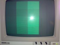
I basicaly combine RGBI via resistor network, feed it into base of a NPN transitor. Two diodes and second transistor are there to combine H and V sync positive pulses and collector of this transistor is conneted to the base of the first transistor, so that it drops to ground when sync. I created little test program that displays four columns, dark grey, grey, white and black , e.g no color modulation needed.
26102013070.jpg

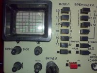
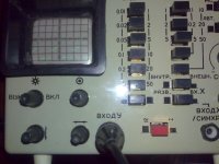
On the antiq russian osciloscope I see similar picture on both the output from a CGA composite out and from my circuit, though not quite the same. The signal period is slightly more then 60us, range from cca 0.1V to 1.8V, that should be fine I believe.

This is CGA's composite out
26102013072.jpg

This is my circuit's out
26102013074.jpg

The monitor works only with the card's composite out signal. With my signal I only see blank screen. At this point I am being stuck. Does anybode happen to have working schematics ? BTW short CGA with RCA composite out would be welcome too.
 
I'm not sure about the transistor and the design will require a +5v signal from somewhere (can the color lines source sufficient power to power the IC?)

How about using a mini-USB header, and powering it with an old USB charger (this is what I've done with the TRS-80 IDE Adapter).
 
Back
Top