There have been a few advances in optoelectronics in the past 30 years, so there should be no need for an external transistor.
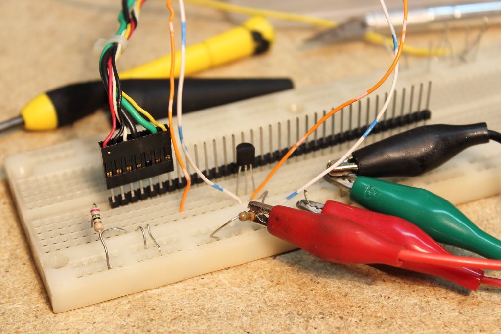
If you want to breadboard it before installing that's ok. Your breadboard need only include a series resistor for the LED and a pull-up for the collector of the opto's output transistor.
Connections are in my post:
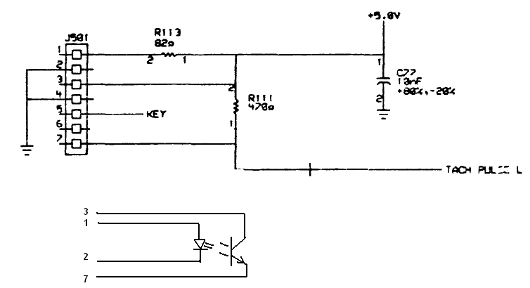
The opto-coupler should be connected as follows:
- Emitter to ground
- Collector is TACH PULSE L - to pull-up resistor (470 ohm)
- LED Anode to series resistor (standing in for R113)
- LED Cathode to Ground
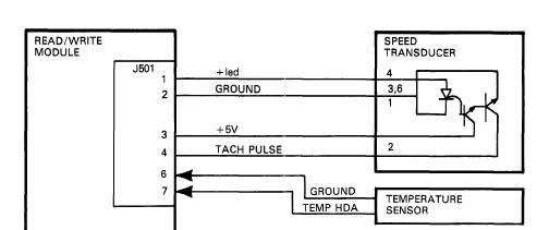
For the actual device cable I expect this would be how to connect it to J501 - The opto-coupler should be connected as follows:
- Emitter to ground J501-4
- Collector to TACH PULSE L J501-7
- LED Anode to J501-1
- LED Cathode to Ground J501-2
As I said - 36ma is too much current for a modern LED. I'd try to size the dropping resistor to 10ma at most, unless the specs for the opto device state otherwise. (LED's usually drop 2v - leaving 3v across the dropping resistor. Size resistor accordingly)
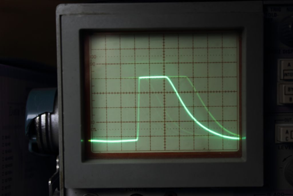
If you breadboard it - you should be able to test the output levels by manually interrupting the path. If this doesn't work, check the LED for output and voltage drop across it should be ~2v.
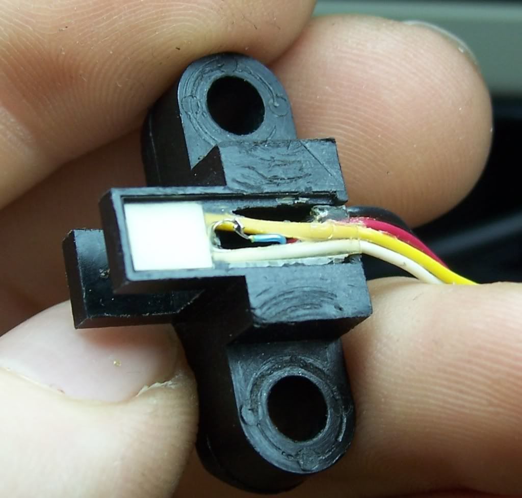
Is there a datasheet for the opto device you bought?
There should be no connection to the opto device's output transistor base. [there may have been in the original]
Sorry for my exasperation.... make that 10000 words.
")