Dwight Elvey
Veteran Member
The input transistor would turn off if you short the leads. The DC voltage you read
is about right, both in voltage and polarity..
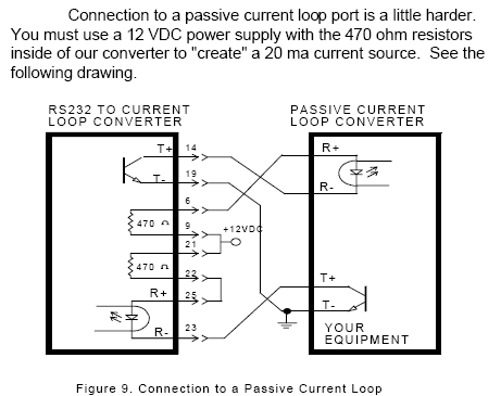
There is not enough voltage in the loop to cause the optical coupler 4100 to operate.
You need to have a separate loop supply. A DC wall wort, a 1000 uf cap and a
resistor to set the current limit, would most likely work.
The resistor would depend on the wall wort voltage. I'd look for a 12 volt one.
Put the capacitor across the leads ( watch polarity ).
Say, after the capacitor was on, the voltage was 15V. I'd try a 750 ohm resistor
first in series. Break the loop someplace and put this in there.
I suspect you'll find things will work as originally suspected.
Dwight
is about right, both in voltage and polarity..
There is not enough voltage in the loop to cause the optical coupler 4100 to operate.
You need to have a separate loop supply. A DC wall wort, a 1000 uf cap and a
resistor to set the current limit, would most likely work.
The resistor would depend on the wall wort voltage. I'd look for a 12 volt one.
Put the capacitor across the leads ( watch polarity ).
Say, after the capacitor was on, the voltage was 15V. I'd try a 750 ohm resistor
first in series. Break the loop someplace and put this in there.
I suspect you'll find things will work as originally suspected.
Dwight