• Please review our updated Terms and Rules here

5150 short +12v to ground... need help

PCFreek

Experienced Member
Joined
Apr 5, 2013
Messages
322
Location
Florida USA
Hi guys... it's been a while. I just pulled all of my collection out and am getting back into this. Funny how much I have forgotten and had to re-learn after taking time away.

I have a 5150 with a 16 to 64kb MB that will not power up. Swapped in a known good later model power supply and the fan will not turn when it is powered up. I have verified that the 3rd pin from the edge of the MB in P8 (+12v) is 0.2ohm to ground. -12v is not grounded. The power supply fan spins with P8 removed and P9 still installed. I have removed one leg of just about every tantalum capacitor on the board.... only the ones below the parity chip in the RAM area remain. I have also removed all cards and all ROMs. I have not removed the RAM.

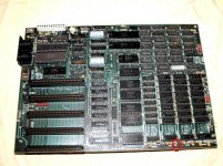
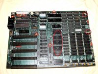
The attached image is not the MB that I am working on, but the red circles indicate what I have removed thus far. I am not attempting to power it up in this state... I am simply testing resistance between pin 3 on plug P8 and ground and still get little resistance. The tantalums that I have lifted a leg on all test good (ohms increase to infinite or extremely high when checked for resistance).

Any ideas? Troubleshooting that I find online doesn't seem to go past tantalums. Thanks!
P1019203.jpg
 
Last edited:
IIRC, those tantalums are three legged, aren't they? So removing just one leg may not have isolated a faulty cap. Try removing two legs from these two in particular:

http://www.minuszerodegrees.net/5150/misc/5150_12volt_caps_plus_minus.jpg

They are all 2 legged. I have also since removed all socketed RAM and the processor. The board is bare. I have also carefully examined both sides of the board for damage or anything that could short between pins on a chip or between solder points. I am still getting 0.2 to 0.5ohm between +12v and ground. Testing resistance between grounds on opposite sides of the board also gets 0.2ohm so this MB is definitely shorted.
 
Last edited:
On the 16/64k board 12V are only used by:
- RAM chips (both soldered and not-soldered banks)
- tantalum capacitors called C6 (there are six, one is for -12V)
- ISA slots (any pieces of metal in there causing shorts?)


My method for this sort of issue is a voltage and current regulated power supply.
- Set it to a few volts
- limit current to maybe 1-2 amperes
- feed the shorted line for a few seconds
- check if something heated up (sometimes a tantalum at fault will just explode)
- if not, repeat with a longer duration

If you happen to own a high precision voltmeter (~6 digits) you can feed the shorted line with a constant current and measure the voltage across every component using the line. The component at fault should have the lowest voltage.
 
The only thing that +12 is used for on the 16-64K 5150 is the Vdd for the DRAM. That leaves only a couple of possibilities.

  • There's something on the board or in the expansion connectors that's shorting things out. Perhaps a bent contact finger in an expansion connector or a stray bit of wire or solder wedged somewhere.
  • A short in one of the DRAM chips (not likely, but possible)
  • A short in one of the DRAM decoupling caps.
  • You missed a tantalum. How about 4 of those near the bottom of the board (in the photo) by the DRAM array? I believe that 4 of those are for +12 and are connected to pin 8 of each DRAM chip.
 
On the 16/64k board 12V are only used by:
- RAM chips (both soldered and not-soldered banks)
- tantalum capacitors called C6 (there are six, one is for -12V)
- ISA slots (any pieces of metal in there causing shorts?)


My method for this sort of issue is a voltage and current regulated power supply.
- Set it to a few volts
- limit current to maybe 1-2 amperes
- feed the shorted line for a few seconds
- check if something heated up (sometimes a tantalum at fault will just explode)
- if not, repeat with a longer duration

If you happen to own a high precision voltmeter (~6 digits) you can feed the shorted line with a constant current and measure the voltage across every component using the line. The component at fault should have the lowest voltage.

I appreciate the advice... I looked into the slots and saw something that looked like a single strand copper wire... appeared to be a hair... dang!!! Went back to caps like Chuck(G) suggested... and...
 
The only thing that +12 is used for on the 16-64K 5150 is the Vdd for the DRAM. That leaves only a couple of possibilities.

  • There's something on the board or in the expansion connectors that's shorting things out. Perhaps a bent contact finger in an expansion connector or a stray bit of wire or solder wedged somewhere.
  • A short in one of the DRAM chips (not likely, but possible)
  • A short in one of the DRAM decoupling caps.
  • You missed a tantalum. How about 4 of those near the bottom of the board (in the photo) by the DRAM array? I believe that 4 of those are for +12 and are connected to pin 8 of each DRAM chip.


Thanks Chuck! I am now up to 54ohm between +12v and ground. Bad tantalum between Bank1 RAM and ground. Bad cap is circled in the photo below. I really don't know why I didn't keep going with caps. I figured that I was chasing a ghost. Now I have to solder all the good ones back in. Thanks again!!!!!! Another early MB risen from the dead. This is an 8140 date code.

Double knock on wood with fingers crossed... I only believe that I resolved the short.. I haven't actually verified it as working... hope I didn't jinx myself.

P1019203.jpg
 
My suggestion is scour eBay for NoS blue tantalum caps and replace them with new ones temporarily. Tantalum caps are measured not by if they will fail, but when. As nuts as I am about making systems restored back to perfect, I always change the tantalum. If I need to I will put temporary ones in while I search for the correct NOS ones.

Cheers,
Corey
 
I'm about to head to Radio Shack to pick up some tantalum caps... It will not boot to a beep in minimum diagnostic configuration. would the cap I removed prevent it from booting?
 
Actually, probably none. However, if you want to make an "in a pinch" substitution, you might try some aluminum electrolytics of the same value. Not the same ESR characteristics by any means, nor high-frequency effectiveness, but they'll do the job in this application.

And lots cheaper.
 
It will not boot to a beep in minimum diagnostic configuration. would the cap I removed prevent it from booting?
No, but many other things can.

If the voltage lines and POWER GOOD line are still not as expected (see [here]), then there is still a power related issue that needs to be identified; more shorted capacitors perhaps.

If the voltages on those lines are as expected, then the following are SOME possibilities:

You earlier (visually) indicated that you removed the BIOS chip (U33) and BASIC chips (U29-U32). Did those go back in the correct orientation, with no bent pins?

You may have had some RAM in bank 0 go bad. The piggybacking technique (see [here]) will sometimes diagnose that particular problem. Othertimes, it doesn't, and bad bank 0 RAM is diagnosed by the use of a Supersoft/Landmark diagnostic ROM placed in socket U33 (via an adapter). See [here].

Some people, including me, have encountered a BIOS chip (U33) that has gone bad.

Tantalum has been replaced and the voltages are all as expected... Power good = +5.07v, the +12v and -12v are +12.15v and -11.93v. Power supply now runs with P8 and P9 connected.
The BASIC chips are different numbers than my other computers, but I am pretty sure that I put them back in the correct order:
U29 - 5700019
U30 - 5700027
U31 - 5700035
U32 - 5700043
U33 - 5700051

I have installed a SuperSoft ROM and a monochrome card and monitor. All 4 banks or RAM are populated. SW1= 1-2 on, 3-8 off. SW2 is all on.
I get no video and no beep codes. I am going to probe or replace the processor next as the Supersoft user's guide indicates clock or processor failure is the next most likely cause of a "dead" MB.
 
That's true, AFAIK. The Supersoft ROM doesn't even need functional RAM to tell you that something's wrong.

If you've got the tools (e.g. logic probe or scope) see that the CPU's getting a clock signal and the address and data lines are twitching. If not, then things get easier. :)
 
The BASIC chips are different numbers than my other computers, but I am pretty sure that I put them back in the correct order:
U29 - 5700019
U30 - 5700027
U31 - 5700035
U32 - 5700043
U33 - 5700051
Correct, according to my notes.

First revision BIOS - nice. Framer was no doubt disappointed to find that chip faulty on his early 5150.

I have installed a SuperSoft ROM and a monochrome card and monitor. All 4 banks or RAM are populated. SW1= 1-2 on, 3-8 off. SW2 is all on.
I get no video and no beep codes.
For information, note that the SuperSoft ROM does not output beeps (of any kind) nor POST codes.
For information, SW1/SW2 settings will not affect the ROM's ability to generate a display.

I am going to probe or replace the processor next as the Supersoft user's guide indicates clock or processor failure is the next most likely cause of a "dead" MB.
Something else you can try; something that mmruzek used to discover that his 'dead' clone 5150 motherboard was working at a low level.
Put the 8KB sized code [here] into a ROM (repeat as many times as required to fill the ROM), and then via an adapter, put that into socket U33.
The code outputs 33 hex to a POST card (monitoring port 80h) and then halts.
 
For information, note that the SuperSoft ROM does not output beeps (of any kind) nor POST codes.
For information, SW1/SW2 settings will not affect the ROM's ability to generate a display.

Something else you can try; something that mmruzek used to discover that his 'dead' clone 5150 motherboard was working at a low level.
Put the 8KB sized code [here] into a ROM (repeat as many times as required to fill the ROM), and then via an adapter, put that into socket U33.
The code outputs 33 hex to a POST card (monitoring port 80h) and then halts.

Supersoft user's manual page 5 "What if my display is not working?" states that the ROM POST module will generate a distinct series of beeps. I do recall the odd beep patterns from the last time I used it.

The user's manual also says on page 8 to ensure that the MB is configured for the display adapter, but I now realize that the diagnostic ROM user's manual can be used for a variety of machines. Good to know that proper jumper selection is not required on the PC in the event I fail to set the switches properly.

Modem7... you know a hundred times more about these PCs than I will EVER know. I hope I can get it figured out with the logic probe... I do not have the ability to make ROMs yet... but I am willing to learn if necessary.
 
The user's manual also says on page 8 to ensure that the MB is configured for the display adapter, but I now realize that the diagnostic ROM user's manual can be used for a variety of machines. Good to know that proper jumper selection is not required on the PC in the event I fail to set the switches properly.
Yes, a problem with page 8 is that the author is sometimes writing about the Landmark ROM ("Landmark's ROM POST") and sometimes about the IBM ROM ("system BIOS").

Supersoft user's manual page 5 "What if my display is not working?" states that the ROM POST module will generate a distinct series of beeps. I do recall the odd beep patterns from the last time I used it.
I was very wrong, and I don't know why. Maybe it was because I have never run the Landmark ROM on a motherboard that had a speaker connected. Still, it never hurts to read the manual.
 
The U26 (74LS175) readings:
pin 1: dead
pin 2: dead
pin 3: low
pin 4: dead
pin 5: dead
pin 6: low
pin 7: dead
pin 8: low
pin 9: pulsing (slow steady flashing/beeping on the logic probe)
pin 10: pulsing
pin 11: pulsing
pin 12: pulsing
pin 13: dead
pin 14: low
pin 15: dead
pin 16: dead

I have previously been advised that pin1 should be high. I am trying to figure out the schematics to probe upstream if necessary. These readings were taken with the Supersoft diagnostic ROM installed. Logic probe powered by +12v from power supply to floppy drive connector.
 
Last edited:
On a 5150 with no good RAM, not only does the speaker beep, but the tape relay also clacks at the same time. Hard to miss, even if there's something wrong with your speaker.
 
Back
Top