• Please review our updated Terms and Rules here

PET 2001-8 Video Display Dead

So far there is bad Vcc on C5 and C6 as well as the pull-up resistor R39. It is probably a break in a power trace, but as you say, the trace should be wider than a signal trace. Didn't Commodore know about ground and power planes for their boards? Or don't tell me this is not a multilayer board??
-Dave
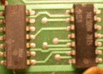
Just plain double-sided. Sorry for the poor quality but you'll get the idea; Vcc and a somewhat thicker GND bus running adjacent to the respective IC corners, with surprisingly few bypass caps:

PET2.JPG
 
I decided to pull the C9 chip and its socket. I put the C9 Chip directly into the spot (no socket)

Something happened after I did that. The monitor tube started making noise, like when it starts to power up. Then I looked at the back of the tube and it was charged. I powered the machine off and the display showed the fade out dot.

Now, when I power up, I can hear a really high pitched whine that changes tone slightly. It's not loud but I can hear it. When I shut the machine off, I get the fading white dot.

I think this is good news. It appears a problem was induced on the +5V by the soldering of the socket. Now with that resolved, and a good counter, you appear to have good Horizontal Drive which will drive the switching high voltage supply for the CRT. However you should have a screen with at least garbage characters.

Do a quick check on the +5V power pins, and then see if you have a good Horizontal drive of 15.625 KHz and a Vertical Drive of 60 Hz. If so, you should be getting video; make sure the brightness is up.

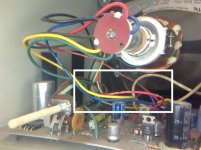
I started smelling burning plastic from the tube section. I powered down the machine and noticed one of the wires going into the back of the tube had begun to melt its plastic coating off.

Here is a pic:
BurningPlastic.jpg


What to do now? Beyond killing myself with the tube. :p
 
What to do now? Beyond killing myself with the tube. :p
Not a very reliable or efficient method; colour monitors are better, especially big ones.

Maybe you should leave the monitor disconnected until we get what looks like reasonable signals...
 
Not a very reliable or efficient method; colour monitors are better, especially big ones.

Maybe you should leave the monitor disconnected until we get what looks like reasonable signals...

YES, disconnect the J7 cable going to the CRT. Check the Horizontal Drive on the J7 header at pin 5. Pin 6 is the pin missing. Is the signal at 15.625 KHz?
 
Do a quick check on the +5V power pins, and then see if you have a good Horizontal drive of 15.625 KHz and a Vertical Drive of 60 Hz. If so, you should be getting video; make sure the brightness is up.
Power is around 4.92 V
the Horizontal Drive is not showing anything, I'm getting some background noise pattern thats erratic and the voltage is 3.91 . With Vertical drive has nothing on it and I am getting 4.2 V
 
Power is around 4.92 V
the Horizontal Drive is not showing anything, I'm getting some background noise pattern thats erratic and the voltage is 3.91 . With Vertical drive has nothing on it and I am getting 4.2 V

Boy that is disappointing. We must have had some horizontal drive there for a moment to generate the high voltage before something happened. What is the color of the burnt wire going to the CRT?

OK, when you are ready, let's start from the top.

Once you are sure we have good +5V, then we start at the top left of the Sheet 3 schematic and check the entire clock countdown chain to see what happened to the horizontal drive. Apparently we never had a vertical drive as there was only a blank screen, but that's something to fix after we get the timing signals working. Keep your spirits up.

After the main board looks OK, and before we hook up to the video board, we need to check that there is not a fault on the horizontal drive load in the video board. Lots to do.
-Dave
 
I know you're having a lot of fun and learning a lot and I can't guarantee that I'd be able to do any better than you, but would you like me to have a look at the board, just in case?

m
 
I know you're having a lot of fun and learning a lot and I can't guarantee that I'd be able to do any better than you, but would you like me to have a look at the board, just in case?

m

Mike,
I think there is a lurking problem of a high impedance short on the power buss in that area of the C row. It is causing the timing signals including Horizontal Drive to be erratic. Possibly it was just a solder splash under the new socket, but the counter was misbehaving before the socket was installed.

I wish I had Wolf disconnect the CRT when we first discovered a potential problem with the H drive. It would have been prudent. The problem of troubleshooting by remote control is that you can't quite tell what is really going on; too much filter. I remember my first reaction to 'magic smoke'. It is very traumatic. Wolf seems pretty tough and I'm sure he will get back on the saddle again.
-Dave
 
As I mentioned in our other current PET thread, I wonder how effective remote diagnostics would be using webcams and voice with something like Skype or Google... Should try it some time, tackle old time problems with modern technology. Hmm, ethernet interface to the oscilloscope perhaps...

As it is, Wolf is only 5 minutes away and Santo less than 1/2 hour along a road I travel frequently, so that's always a last resort for whatever it might or might not be worth...
 
As I mentioned in our other current PET thread, I wonder how effective remote diagnostics would be using webcams and voice with something like Skype or Google... Should try it some time, tackle old time problems with modern technology.

I'm game. No one can call me "Totally Obsolete". They can only say 'mostly obsolete'. ;)


Hmm, ethernet interface to the oscilloscope perhaps...

You are right. Here is a blurb I found on the Tektronix site.

"INSTRUMENT CONTROL


Utilizing the built-in ethernet port, e*Scope web-based remote control allows you to a control TDS3000C series oscilloscope from anywhere, using the internet and your PC."


I would guess one could see the display remotely too. Of course these scopes cost a pretty penny.
-Dave
 
I would guess one could see the display remotely too. Of course these scopes cost a pretty penny.
-Dave
Yeah, but what (if anything) could you do remotely with those cheap PC-based 'scopes? Not much bandwidth, true, but might be enough to get a rough idea of what's happening...
 
I'm sure a lot of what's happening is my lack of understanding (electronics wise) coupled with a few possible bad assumptions on my part at the beginning.

If you want to come by, I'm all for it. I'll just have to man up and accept the ridicule of my horrendous soldering job. Breadboards killed the soldering star.

I do have a Skype account, web camera and few other cameras to act as remotes. I could strap a camera to the scope output.

I could record a video of the process as well and post it.

Until my shame is public, what shall I measure next?
 
what shall I measure next?

Wolf,
Until Mike and you get a new plan, first makes sure the +5V is OK on the C row.

Then we'll start checking the clocks. First the 8MHZ buffered output at E2-pin 6. Your scope will have a little trouble with that frequency but you can tell that a high frequency clock is running.

Then work down the schematic with the outputs of counters C9 and B5. At B5-pin 11 you should have 31.25 KHz. Next the Q and Q BAR of C7 should be at 15.625 KHz, the horizontal drive frequency. All the above clocks should be square waves. Those following will not be square waves.

Next check C5 pins 5 and 6 are pulsing at 15.625 KHz. These are the horizontal display ON and OFF signals.

Lastly if all this is working, you should have Horizontal Drive at C5-pin 2 at 15.625 KHz.
 
Last edited:
All the +5v in the C section are fine.

Next is a Scope question. My little mini scope is totally messed up. Do you have a suggestion for a decent scope? Rigol DS1000E Series or OWON SDS5032E is what keep seeing on the net.
 
Next is a Scope question. My little mini scope is totally messed up. Do you have a suggestion for a decent scope? Rigol DS1000E Series or OWON SDS5032E is what keep seeing on the net.

I would be very patient and look for a local Tektronix analog scope like a 465 or 454. Make sure you see it working or photos of both channels working with right to return if not working, and if it has to be shipped, make sure vendor will package it properly (foam in place, or double boxed, etc). Keep looking until you find one in your price range. They can range from $125 to $500 plus shipping. A local pick up would be best so you know its arrives in one piece. They are fairly small and perfect for vintage computers.

I am not too familiar with the little DSO gadgets but if you have your heart set on one, I could do a little research on their specifications. You would want an equivalent analog bandwidth of at least 30 MHz on two channels for looking at 8 MHz TTL signals.
 
I'll try to scrape up a 465, I've a 475 availabel recently for around 200$.

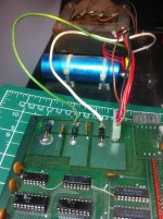
On other news. I was looking at other pics of boards, similar to mine. I noticed a difference. Whoever had it before wired extra lines to the mainboard..
PowerSupplyWiring.jpg

Next, I spent some time looking at all the power supply voltages to everything. The majority of the chips measure 4.92V, but anything in the area of: Slots H-G rows 5-9 measure 5.04V. Might have something to do with the extra wiring? Should I remove that extra power wiring?

Until I get a scope that works, I guess I have to wait on what to do next.
 
I'll try to scrape up a 465, I've a 475 availabel recently for around 200$.

The 475 is is good scope also with a bandwidth of 200 MHz which is better than the 465.

On other news. I was looking at other pics of boards, similar to mine. I noticed a difference. Whoever had it before wired extra lines to the mainboard..


Next, I spent some time looking at all the power supply voltages to everything. The majority of the chips measure 4.92V, but anything in the area of: Slots H-G rows 5-9 measure 5.04V. Might have something to do with the extra wiring? Should I remove that extra power wiring?

It looks like a previous owner needed to beef up the +8V unregulated power and the ground from the big capacitor to the board for some reason. Perhaps the power connector is worn and not making good contact. We should find out why the C row has only 4.92 Vcc rather than the proper +5V. There may be a bad trace or a chip is drawing too much current. Did you determine that all the +5 V regulator outputs were at the proper +5V?
 
Power2001-A1.jpg

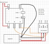
Well I thought the power was acting kind of weird. So I mapped out the transformer up. I removed the extra power connections as well. If they are beefing something, it might mean there was a problem with something else. The plastic connector for the cable going into J8 has seen some heat, there is some head damage on the two middle pins.

Is this wired correctly?
 
Back
Top