• Please review our updated Terms and Rules here

PET 2001-8 Video Display Dead

wbochar

Experienced Member
Joined
Aug 2, 2014
Messages
77
Location
Toronto
I've got a PET that was really in bad shape (bird nest and all), he was in storage for a while and last week I pulled him out to work on him.

He worked fine for a few days, the first thing was getting the RAM to work properly -- there was few bad chips. Testing was swapping around till I got around 6k. the last two chips I swapped into video ram to see if both were bad. Both were bad.

I've got a site that I am keeping my notes at, which while I was updating them -- the screen died.

PET 2001-8, found in Toronto, Canada
6/8k Working
Has Full PET ASCII Keyboard, Non-Tape Drive model.
Logic Assembly: 320132
Has Original ROM's

So I wasn't sure if something on the main board died, so i started checking ROM's and Ram etc..

Well This is boot up...

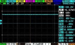
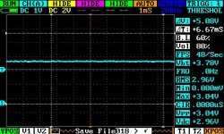
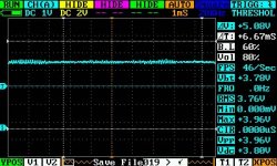
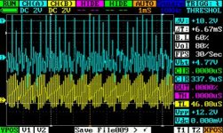
CH(A) (TOP) is Pin 1 off of the 2114 SRAM in the first bank.
CH(B) (BOTTOM) is PHI2
RAM-PL2.jpg

Well, it's got a pulse.. hah.

I think it's actually the display system itself. The monitor is not powering up or showing the signs when it's powered off.. The Fading white dot..

It looks like the tube doesn't power up at all. With an induction amplifier, aiming it at ANY CRT will be noisy as hell. My 1084 monitor generates a lot of noise, and a PET monitor should be loud... not a peep.

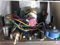
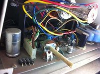
Opening the back:

It looks ok?
MonitorOpen1.jpg

MonitorOpen2.jpg

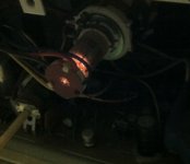
TubeLit.jpg

This last pic is with the light off, to see that the tube is actually got something going on.. The tube is lit when the power is on, just not enough to show something.

I have this weird feeling that opening and closing the case continuously (during my ram and rom testing) may have jarred something. Part of me thinks that whatever is driving the tube doesn't have enough power to bring it up.

I have my notes at http://wbochar.com which has more pics of the MB etc.

Thanks for reading,

--Wolfgang Bochar
 
Hi,

just a thought about that.

I don't remember if the 2001/8 CRT assy is similar to the 8032 one, but: I had a similar problem with one of my 8032s: motherboard ok, tube ok, tube neck lit (like the one in your photo), etc. --> after some hours spent testing everything, I discovered there are some resistors made by wire that are mounted raised, with a pin far from the pcb. They act like fuses, in someway. One of them was broken and the CRT was dead. Replacing that resistor solved the issue.

As told, I don't remember if the 2001/8 uses the same tecnique in its CRT assy (sorry, too lazy to open mine and verify ;-) )

cheers,
Giovi
 
If the horizontal drive signal is not running at about 16 KHz from the main board, there will be no high voltage for the tube.

The main board, the connector going to the Display system:

1 O Video
2 O GND
3 O Vertical Drive
4 O GND
5 O Horizontal Dive
6 - (No Pin)
7 O GND

I get 4.08V off Pin's 5/4 but the scope just flatlines. Other mainboard components show activity, but the horizontal and vertical drives don't. Any suggestions where to go next?
what does pins 5/4 mean? Pin 5 with respect to pin 4?

anyway this will be easy to fix as these signals are generated with a few flip flops. Get the correct schematic from zimmers.com. We'll start with sheet 6 at the lower right and trace back the horizontal signal. Can you find chip H7?
-Dave
 
No, I had wrong schematic for your machine. Look at top right and follow horizontal Drive back to flip flop C5 pin 2. If not a 16 KHz waveform, look at J and K inputs for 16 KHz pulses. They are the Display ON and OFF signals.
 
I've got to head out for work, i'll be back to try this out in 2 weeks. Thanks for the tip, I'll et back to you :)
 
I've got to head out for work, i'll be back to try this out in 2 weeks. Thanks for the tip, I'll et back to you :)
Give me a shout when you get back; maybe we can figure this out together.

BTW, those are pretty short pulses and easy to miss if your trigger an sweep aren't appropriately set.

m
 
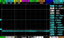
C5_PIN2.jpg
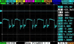
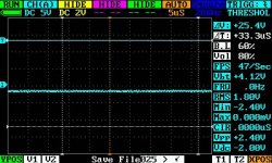
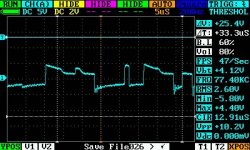
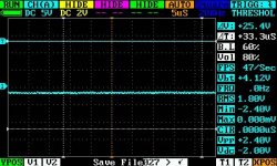
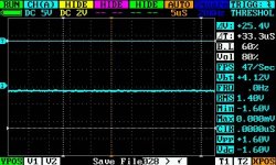
This is what I get on C5 Pin 2, similar results appear on Pin 4. I powered up the machine and monitored the pin's with each power cycle. I attached the monitor cable and removed it to see if that affected the results. Same.

I also noticed something weird, I hooked up my C2N to a C64, recorded and a test program. I then mounted the C2N on the PET's rear tape connector and powered it up. I typed load and hit play and then enter. A few different combo's.. I also notice that I could not rewind the tape or fast forward it. the transport controls work on the C64...

I moved the C2N to the internal cassette port, which if the transport controls are engaged (FF,REW,PLAY) when the PET powers up, they work for about 3 seconds then stop.

Maybe that helps with the diagnostics.
 
Last edited:
This is what I get on C5 Pin 2, similar results appear on Pin 4. I powered up the machine and monitored the pin's with each power cycle. I attached the monitor cable and removed it to see if that affected the results. Same.

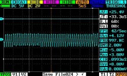
Maybe you are lucky and the C5 JK flipflop is bad. To make sure, see if there are 15.625 KHz waveforms on JK inputs pins 1 and 4. And a good 125 KHz square wave clock on pin 12. If so, or unless the the C5-2 output is shorted to ground by something else, then the C5 74LS107 flip flop is bad.
 
C5-PIN1.jpg
C5 PIN 1
C5-PIN4.jpg
C5 PIN 4
C5-PIN12.jpg
C5 PIN 12

Can I test the flip flop with the pet off, using some external power and pulse generator?
 
It looks like something in the basic clock countdown chain is out. This should be easy to spot. Before you start make sure the scope is working and also set the time base to around 1 microsecond not milliseconds although it may not be critical at this point as all you are looking for right now is a clock signal or no clock signal.

chip/pin SIGNAL
E2-pin 6 8 MHz
C9-pin11 1 MHz
C9-pin12 500 KHz
B5-pin14 500 KHz
B5-pin12 250 KHz
B5-pin 9 125 KHz

Maybe you should check the source of the CPU Phase 0 clock input at C8-pin 6. It should be 1 MHz. Without that the CPU will not run at all.
 

Wolf,
OK, the clock to generate the C9-pin12 (0.5MHz) signal is fine so it's starting to look like like C9-pin12 is dead. Since it is low, there is a small chance that something is holding it down (short). Take a quick look at it loads at B5-pin14 and C5-pin9 for solder splash, etc. If nothing obvious then you will have to replace the 74LS93 counter (C9).

If you are not experienced with replacing a 14 pin IC, it will be easier if you use a small diagonal cutter to cut off all the legs as close to the IC body as you can to leave legs accessible at solder joints. Then using solder wick, remove solder and leg using needle nose, etc., one at a time using minimum heat. This will allow removal and cleanup of solder feedthroughs with minimum chance of overheating the printed circuit board and associated traces.

You might consider installing a socket first rather than installing the new chip directly in.

If this fixes the clocks, you will have good video horizontal & vertical drive signals. The horizontal drive will also be used as the switching signal to generate the high voltage for the CRT. You should then have an operating CRT. We can then go on to whatever the next issue is with the PET if any.
-Dave
 
Thanks a lot for the hand holding :)

I'm decent with a Solder gun. But before soldering I'll check the board again with a magnifier. I have to say I've learned a lot from this and its amazing to learn new things :) I'll get back to you with my findings :)
 
Take your time; you will do fine. As crude as they are, the Commodore printed wiring boards are pretty tough and can handle some heat. Use a soldering iron rather than a gun if you have one. The old solder guns put out a lot of watts.
 
Back
Top