• Please review our updated Terms and Rules here

8272 FDC to 8" drive connections

Note that while the switcher rates max voltage at 60vdc, you can't or couldn't get a zener to properly protect it at that rating

I'm not sure that I follow. I have 200V TO-3 zeners; my UPS battery is protected with a 50V 50W zener.
 
I don't know. Sounds expensive. I don't have to worry about anyone stealing my designs, they don't work that well in the frist place and who would want 40 year old stuff anyway. How much would you think a S-100 size board would cost? Figuring that there may be 500 holes? I really doubt that this is within my purview. But I'd like to think about it. Thanks Mike
 
For a one-off S-100 with through-hole, I don't think it's worth it. Back in the day, wire-wrap worked fine for this kind of stuff--even the original IBM PC was prototyped with wire-wrap--and tons of ECL stuff.
 
Last edited:
Thanks for looking into the price. I'm unaware of these 'chat rooms' your mention. Sounds a little sorted. Can you be a little more specific with a link? You also have to remember that I'm just a 'hack' and most everything I make needs changes on changes, so anything that would be new is subject to not working at all. But what does work could be cleaned up and solidified some. Which may make things run better. This might be a good winter project for 2015-2016, if I'm still around. Thanks for the help. Mike
 
Really, all you have to do is look in the back of EDN or Electronic Design for Custom PCB services.

There are several online cost estimators. Here's one from Futurlec I've used Sunstone, they're pretty good--and they have an online form for quotes--and they offer PCB123, their own design tool--for free.

One caution--the price of a board has a non-linear relationship to the size of the board and the number of vias and holes.
 
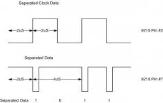
My parts showed up in the mail and I believe that I have the power supply problems behind me. I also took some time to rebuild my FDD power supply. It would not have won any awards for the shape it was in. Now I have some pretty good power with only a little noise. I also received the WD9216 Phase lock loop. I got that wired in the circuit . This morning I connected up Drive and loaded the program. I wanted to see how the PLL worked. I looked at the separated data and clock pins 2 & 7. I could not get the scope to trigger properly to get both of these signals sync together, but I think what I did get is correct.
Waveform.JPG

The separated clock is a square wave with a period of 4 uSec and the separated data is pulses. When there is a pulse that is a data ONE and no pulse is a data ZERO. Now, the program and the FDC board didn't save any data to memory, something else is wrong, BUT, I pretty sure that I'm getting data and clock pulse off the drive and into the 8272 FDC. This is a definite step forward.

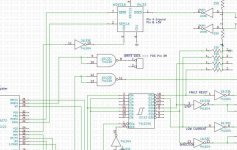
I do believe that I have the PLL wired wrong to the FDC. I have the 9216 Pin 7 Separated data going to the FDC RD DATA, Pin 23. I think that Pin 23 should get the RAW data from the FDC. I' m still looking around for that. Anyway, making progress. Mike
Schematic.jpg
 
Well..... Once again I'm confused and having trouble straightening it out. This is in regard to the connection of the WD9216 data separator. The Intel 8272 data sheet says that the pin 23 RD DATA contains both data and clock bits, or to me that means RAW DATA. In the NEC 765 datasheet seems to indicate that RD DATA should be separated data. So I've tried both and I can not get either to work. Both connections causes an FDC error but they are different.

When RD DATA is connected to RAW DATA from the FDD, after a READ command Status Register Zero has 100 (octal) which means "Abnormal termination of command". Status Register 1 has 004 which means "Sector not found", either it can not find the indicated sector or it can read the ID field. There are no errors listed in ST2 or ST3.

When RD DATA is connected to Separate Data from the FDD, after a READ command Status Register Zero again has 100 (octal) which means "Abnormal termination of command". Status Register 1 has 001 which means "Missing address Mark". There are no errors listed in ST2 or ST3.

I've checked the parameters in the command phase of the read to be sure that I have a valid drive, track and sector number. I know that the disk data is good because I can read the disk on another computer.

The READ parameters that I used are;
command code 0000 0110 READ Command
0000 0000 One Head Drive 0
C 0000 0000 Track 0
H 0000 0000 Head 0
R 0000 0001 Sector 1
N 0000 0000 Sector size code
EOT 0001 1010 Last Sector number 26
GPL 0000 0111 Gap length 7
DTL 1000 0000 Special sector size

I'm not sure that I understand the difference between these errors. I'm also confused as to the 9216 connection, although, NOW, I think that pin 23 should be separated data. Any ideas? Thanks, Mike.
 
I've been reading about the 3740 IBM Format and have found that there are four difference address marks. The FDC detects these address marks because certain data cells will not have clock bits in them. All other data cells will have clock bits. The address marks are
1. Index Address Mark, there is only one of these marks on a track. It comes right after the index hole and preamble gap.
2. ID Address Mark, each sector has one. The track and sector numbers and checksum follow the ID mark.
3. DATA Address Mark, each sector has one. The actual data and checksums follow the DATA Address mark.
4. DELETED DATA, don't know much about this.

The 8272 status register ST1, bit zero, is called "Missing Address Mark" apparently if the FDC can read either the ID or DATA address mark this bit is set.

The 8272 status register ST1, bit two, is called "Sector not found error" I'm guessing here, but I think that maybe the ID and DATA address marks were found, but the actual sector number after the ID Address Mark was not found.

Again I'm guessing here, but I think that the Missing Address Mark error is a more basic error and the Sector not found is not. Meaning the if the sector not found occurs at least the address marks were read.

Is my thinking right here? Mike.
 
Yes, you've got that correct.

Pin 22 on the 765 is actually something called "window" on the NEC datasheets, bit the idea is the same-you feed it from the SEPCLK of the 9216. One thing that you may have overlooked is that the SEPD output from the 9216 needs to be inverted before it's fed to pin 23 of the 765.

The FDC raw data should never directly reach the 765. Maybe this will help.

Here's a datasheet that shows why the SEPD/ signal needs to be inverted for the 8272/765.
 
Last edited:
I think the reason that it's not mentioned is that the Western Digital FDCs (17xx, 27xxx)) require the inverted separated data input, but the 765 uses a positive logic input.

Go figure.
 
I added an inverter in the separate data line between the 9216 Pin 7 and the 8272 pin 23. I tried a read and I still received the same FDC ERRORS. Address Mark not found. So I wrote a short routine to READ ID. The way I understand this command from the datasheet, this command should report where the head is at any particular time? I was a little confused by the fact that the chart said the ID information would be in the data register. I wasn't sure if I had to read the data register after the command completed and get that actual data in the ID field or if the information is just what is retrieved in the result phase of the command, C H R N. I did both.

First, and encouraging was that I didn't get an FDC ERRORS of any kind. The C H R N reported that I was on track zero, which was true (maybe later I try this again on a different track), the head was zero (there is only one), the sector would change each time I ran the sub routine. This seems normal in that the READ ID reads the first id mark it comes across, which would be random. The N sector size read zero, and that puzzles me a little. N should be 128 (200 Octal). I also read the data register after the command completed and this was always zeros, so I don't think this is valid.

So.... I believe that the READ ID command is working, but why should the READ report the ID Mark not found? I'm going to concentrate on looking at the READ command programming, maybe I have something wrong here. Mike
 
Hooray! I got a data transfer from the drive into memory. Not sure whether the data is correct. But, I got 128 bytes in the correct location and the data is all 345 (Octal). Here's what the problem was, and I don't know how many times I looked right at it and missed it. The SECTOR SIZE N is a code and not the actual value. I had 200 (octal) in this spot. When I changed it to the code 000, the transfer occurred. It's magic. Now I will try to read more sectors and determine whether or not the data I'm getting is correct. Thanks for the help! Mike.
 
So.... I believe that the READ ID command is working, but why should the READ report the ID Mark not found? I'm going to concentrate on looking at the READ command programming, maybe I have something wrong here. Mike

Yes, it seems that you've discovered the reason. The READ/WRITE commands compare all 4 bytes of the address against the ID field on the disk track. The interesting part is that the CHR numbers don't have to correspond to any physical reality. You can easily format an ID field that says it's Cylinder 202, Head 52, Sector 86 on any track on the disk, for example. All that's needed is for the 4 bytes in the read command to match the values in the ID field.

If you wanted to be exotic, you could have several sectors on, say, track 5, with the address 5,0,1 -- but different lengths. If you play with the FORMAT TRACK command, you can have all sorts of fun, including putting a sector inside of a sector.
 
Last edited:
Mike_Z said:
..the data is all 345 (Octal)...

That looks like E5 hex which is often used as the formatted sector data until written over.
 
Well..... today I tried to read multiple sectors, but it didn't work. For some reason I could read one sector but not two. I kept getting over run errors. So I figured it was something with the DMA and it was. I had either forgotten or didn't understand that once the terminal count is reached on the 8237 an EOP is issued and this sets the TC bit AND masks the active channel. No wonder it wouldn't work again. So I had to change my SETDMA routine. Now it sets the DAM Address, terminal count, enables DMA and unmasks the channel. So I was encouraged in that I could read two or more sectors all in a row. But, for some reason it was not consistent. Sometimes the program would read everything others not and once in a while it would hang. Well, turns out I had an error in my FDC READY routine. The computer must be a little faster than the FDC, imagine that. After repairing the ready routine, the reads were working like a champ. I added a routine to read multiple tracks and this worked also. The next question is why is all the data 345 (Octal) is the disk blank? Dallas mentioned that 345 is the format filler, so I think I'm reading data. Next I'll have to use IMD to check the disk and see if I can write some data on the tracks I'm looking at. Maybe I can just change the format filler byte. Anyway, thins are looking up. Mike
 
The usual method for low-level formatting of CP/M disks is to write hex E5 in all sectors. CP/M is set up to use this byte as a directory "not used" flag, so it all works.
 
Mike_Z said:
... JDallas mentioned that 345 (E5 hex) is the format filler, so I think I'm reading data...

Yes, it looks like you are reading valid data. That's what I meant.

Sounds to me like you're doing very well.

I haven't done what you're doing now since 1983 when I was testing the prototype of the SD System Versa-Floppy-Winchester III (aka VFW-III). You can see a couple of images of that product advertisement in my VCF Albums (named "Universal Null Set")

Get bold now... Time to write a sector and then read it back. A good start test pattern is 00,01,02 etc. You'll be able to tell quickly if the sector is framed wrong and any point in the process from processor to FDC and then back to RAM via DMA.

How fast is your micro (6Mhz?). It would be better to understand absolutely why the previous version was too fast and needed mods. You want to get it done so its 100% reliable, not tuned to work a lot of the time.
 
Last edited:
When you're reading the detailed status bytes, insert a couple of microseconds delay between reading a status byte and testing the general status register for data available. It takes a bit of time after each status byte is read for the next one to be ready. Just one of those little quirks of the 765--although that shouldn't be a problem with a 2MHz 8080A.
 
Last edited:
Back
Top