• Please review our updated Terms and Rules here

RK8-E Repair

m_thompson

Veteran Member
Joined
Jul 8, 2014
Messages
1,998
Location
Rhode Island, USA
I bought an RK8-E board set through eBay, knowing that at least one board will need to be repaired. The M7104 board has lots of wiring ECOs applied, including adding a 100 ns delay line to the top right of the PCB. The delay line was ripped off the M7104 that I have. The prints say that the part is a DELAY LINE, 100 NS, D-10100 P/N 1609559.

Google says that there is an NSN number for the part, and it was made by Nytronics.
I might be able to get one for a large sum from a military parts broker.

Can anyone send me a high resolution image of the part of the M7104 that contains the delay line?
Any idea where I could get a replacement delay line?

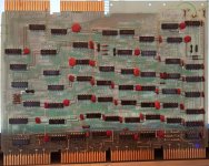
I have a board here with over a dozen wires and the delay line still on it I can take a photo, but I am not sure how much help it will be. There are four holes drilled, one for each lead, and the green wires disappear under the package where they are soldered to the delay line leads. The leads are bent over, and the two ground leads are soldered together, to help anchor the part. There are two 1K resistors connected to it which have been added in a similar fashion.

The delay line itself was also used elsewhere. I'm quite sure I remember adding it to my parts library, though I don't remember offhand which boards used it. Maybe there's one going spare on an old flip chip module somewhere.

Vince
 
Vince,

Maybe you could put high resolution images of all three boards on your WWW site.
I will make a list of the added wires on mine, and where they go.
 
Can anyone send me a high resolution image of the part of the M7104 that contains the delay line?
Any idea where I could get a replacement delay line?

It is on the RK8J-E engineering drawings which would make sense if this is the board set that Will was just selling.
You might look around the surplus places or use one of the Dallas Semiconductor IC delays. It isn't tapped, so it
should be fairly easy to find. I think there is an old Pulse Engineering catalog on bitsavers.
 
Vince,

Maybe you could put high resolution images of all three boards on your WWW site.
I will make a list of the added wires on mine, and where they go.

OK, I've created directories and put some photos there:
http://svn.so-much-stuff.com/svn/trunk/Eagle/projects/DEC/Mxxx/M7104/
http://svn.so-much-stuff.com/svn/trunk/Eagle/projects/DEC/Mxxx/M7105/
http://svn.so-much-stuff.com/svn/trunk/Eagle/projects/DEC/Mxxx/M7106/

I found two instances of the M7104. One calls itself "B2", and seems to at least have the delay line mounted straight :).
Let me know if you need a close-up or anything.

Vince
 
Al, I actually have a tube of PCA EP19825 100 ns tapped delay lines. Maybe I could just use the input and output pins and ignore the taps to get the 100 ns delay.
Vince's RK8E.pdf is revision A. It would make a nice addition to the documents on Bitsavers.

Vince, my M7104 says B2 in etch on the back. The rework on the front side is a little different from yours. The added resistors are in different locations, and it looks like the delay was also in a different location. I will take pictures of it.

I need to get an M993 to connect to the RK05 drive. I can probably make one out of a W999 if I can't find one.
 
The delay line itself was also used elsewhere. I'm quite sure I remember adding it to my parts library, though I don't remember offhand which boards used it. Maybe there's one going spare on an old flip chip module somewhere.


Found it. Each M104 uses a pair of them. I do have spare M104, if you need to scavenge one.

Vince
 
My M7104 doesn't have the two handles installed, or the three electrolytic caps near the Omnibus connectors. It also has "BAD" written on it.

There is an added wire that grounds E42 pin 6. This is OK, but E42 pins 5 & 6 are tied together on the PCB, and separated on the schematic. Grounding E42 pin 6 would ground the MD RL L signal.

There is an added wire that grounds E15 pin 5. This wire goes into a plated through hole for one of the missing electrolytics so it is not grounded. E15 pin 5 & 11, and E42 pin 6 are interconnected and then tied to ground. Without this ground connection the board will not enable the MD6, MD7, and MD8 signals onto the board.

Maybe DEC never finished assembling or debugging this board?
 
Will is selling another RK8-E set as well. This one has even worse damages in the same corner of the board. I just wonder what has happened to these board set? In the same a area on the same board?
 
The TD8-E that I have would never have worked the way that it was assembled. It had a repair tag on it from 1972? that said "doesn't write".

The M7104 that I have was never finished. The handles and the electrolytics near the Omnibus connectors were never installed. The location of the delay line and added resistors is different from the production boards.

Maybe these broken boards were scrapped by DEC and are now finding their way to the market?
 
Gents,

I'm not sure if this is any help (I'm a little late), but is the ECO work on my M7104: http://www.vintage-computer.com/vcforum/album.php?albumid=43&attachmentid=22714

The handles show this: http://www.vintage-computer.com/vcforum/album.php?albumid=43&attachmentid=22713 . It's a little hard to read, but initial build was 9/28/73 (73 week 44 on the handles). It had started as code D on etch revision A, then ECO upgraded to F, K, and I think I see a hand scribed Z (really not obvious on the photos, only only on one handle. Was Z usually affixed when there was a non-standard modification?

Lou
 
Last edited:
Gents,

I'm sorry I keep editing this post, but I keep reading more closely and should make fixes...

I dug through some of my hardcopy print sets and found the M7104 Revision CS rev B and K prints. M_Thompson, you must have at least B rev prints to know the details on DL1. Thess revs shows the delay line ECO, but Vince's rev A prints do not. It looks like the delay line add was the very first ECO as I read the bitsavers ECO log closely.

The rev K drawing date is 6 May 1976. It's ECO M7104-00008. Does anyone have a late DEC-O-LOG for M7104? The one on bitsavers only goes to ECO -00005.

Lou
 
Last edited:
I have the Rev A assembly Rev B etch M7104 prints from Vince that added an RC delay between E37-11 and E40-05 for the 6RK2 L signal.
There is also an annotation on this print about disconnecting the enable signal for E42 from the MD RK L signal and connecting the enable to ground.

The RK8J-E prints have a Rev K assembly that uses Rev B etch M7104.
This set of prints has LOTS of modifications, and replaces the RC with a 100 ns delay line.
Vince has a board that looks like this one.

My M7104 PCB is etch B2 and looks almost like the Rev K assembly.
It is missing some cuts that are shown on the print, and one cut that should be on the print.
 
I started reading through the DEC ECO log for the RK8-E. It looks like there are ECOs for the M7104 that are later than the latest set of prints that I have. These M7104 ECOs depend on ECOs that need to be done to the M7105. There are also notes about compatibility issues with certain revisions of the M8330 processor board.
 
No delay line, missing a few bypass caps, and no handles.

There are some added wires that share holes with the missing bypass caps. These are not soldered.

Makes me think that the board failed test in manufacturing and was never finished. The TD8E that I have had a capacitor in the wrong place and never would have passed diags. Maybe a bunch of the boards that are now showing up on the market were scrapped by DEC and should have been destroyed.

RK8-E Front Missing Delay.jpg
 
Last edited:
Back
Top