• Please review our updated Terms and Rules here

Altair 8800 with Z80 CPU wont toggle anything. Help!!

Hi All;
Jean-Luc, "" due to volunteer work becoming work work. "" Good for You !!!!!!!!!!!!!!!!!!!!!!
I Would Order and Replace the Capacitors before it gets any worse.. Glad You Caught it before it gets worse..
"" I'll let you know when I'm working on it again, "" Please do that..

THANK YOU Marty
 
I double checked my voltages on the bus, and found something interesting. i have the proper voltages for +8A and +8B.....but for the + and - 15v on pin 2 i only have +11.9v and on pin 52 i have -18.4v now if pin 2 requires +15v (and I'm only getting +11.9v) and pin 52 requires -15v (and I'm getting -18.9v) can this be the source of all my problems with getting it to deposit and perform proper functions due to the lack of +15v by about +3v? On the first day of putting the pieces of the Altair back together i had to replace one of the linear transformers to get it to power up. I replaced the 110v transformer with the P/N 102609 in the assembly manual with a RadioShack Transformer with Pri.120v and Sec. 12.6 -0- 12.6 2A Specs. could that transformer be my problem also? do i need to get a different transformer? If so, what liner transformer do you suggest? I know that switching power supplies would be better and safer, but I don't want to go that route at this time. Maybe in the near future but just not right now.

Edit: Well crap!! I tried applying the +15v by an external source (a voltage adjustable switching power supply) I even measured the voltage BEFORE putting it on the terminal block where the +15v connects to it from the PS Board. What i didn't take into account is that the PS Board might be running the +15v THROUGH the diodes, resistors and capacitors BEFORE it comes off the board and onto the terminal block. I'm gonna be honest and admit that I'm still learning about how different circuits work, but I'm pretty sure that what i did was probably pretty stupid, because when i turned the computer on, smoke started coming from what looked like a diode or two so i turned it off quickly and immediately unplugged it from the power strip. Granted I needed to replace all of the diodes, resistors, and capacitors on that board anyway, now i need to do it before i can work on the computer again. :(
 
Last edited:
Hi All;
K1atn, Welcome Back..
"" . I replaced the 110v transformer with the P/N 102609 in the assembly manual with a RadioShack Transformer with Pri.120v and Sec. 12.6 -0- 12.6 2A Specs. could that transformer be my problem also? do i need to get a different transformer? If so, what liner transformer do you suggest? ""
It all depends on what was there before.. If it was 12.6 then, for now the Amperage would matter..
"" What i didn't take into account is that the PS Board might be running the +15v THROUGH the diodes, resistors and capacitors BEFORE it comes off the board and onto the terminal block. "" Yes, they are used to give the correct output..
"" I'm gonna be honest and admit that I'm still learning about how different circuits work, but I'm pretty sure that what i did was probably pretty stupid, because when i turned the computer on, smoke started coming from what looked like a diode or two so i turned it off quickly and immediately unplugged it from the power strip. Granted I needed to replace all of the diodes, resistors, and capacitors on that board anyway, "" yes, that would be the best course..
"" I'll let you know when i've got everything replaced on the board. "" OK

THANK YOU Marty
 
Success!! Somewhat anyway. I cleaned my local RadioShack out of diodes, resistors, and what they had left of capacitors as they were going out of business, and managed to get all 10 diodes, all of the resistors, one 2200mfd capacitor, and i replaced one of the 0.1mfd ceramic capacitors with a 0.01 mfd capacitor. Anyway, i replaced all of those on the PS Board with new ones, and Voila!! The Altair powers up yet again!!!! Unfortunately though, it's still only giving me 11.4v on pin 2. Everything else is fine.

Any suggestions about that low voltage?
 
Hi All;
K1atn, first, If You have Not done so.. PULL all of the Boards Out of the Machine, and them measure the Voltages..
And see if any of the Boards are or is pulling the voltage down,, Also check ALL of the surrounding pins and make sure that the --18 volts is not leaking to another pin..
Also Double check that the PS board has or is wired correctly..
Check that R4 is Correct, it should have one side to Ground and the other side to --18 volt line, make sure it DOESN'T have one side to --18 volts and the other side to the +18 volt side..
Looking at my Schematic for +18 and --18, the Radio shack Power supply should be OK for the --18 volts..

THANK YOU Marty
 
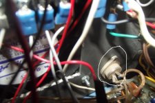
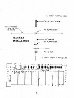
Marty, when i took those voltage measurements, there were no boards plugged in, and no load on the unit. I did check the surrounding pins, and there doesnt seem to be any leakage. as for the PS board being wired correctly, it appears to be. Although i have found that there is an added something that i cant find in the manual attached to the back chassis, with wires going to the place i circled in the manual photo. Also I circled the component that is wired to the spot on the page of the manual i posted. Could it be my problem? Should i cut the wires and remove it? BTW WITH both boards plugged in the voltages measure pin 1 and 51 +8.3v pin 2 gives me 13.8v under load versus 11.4v without the boards in, and pin 52 is -18.4 under load. As for R4 being correct, it appears so.

DSCF2168.jpg

Altair.jpg
 

Attachments

  • Altair.jpg
    Altair.jpg
    82.1 KB · Views: 1
Last edited:
Hi All;
K1atn, "" Marty, when i took those voltage measurements, there were no boards plugged in, and no load on the unit. "" Ok..
"" I did check the surrounding pins, and there doesnt seem to be any leakage. "" OK..
"" as for the PS board being wired correctly, it appears to be"" Appears, may not be the same as IS.. Check the --18 Volt Circuit.. IS it the same as what is shown, or not.. "" As for R4 being correct, it appears so. "" Is one side Grounded or not and the other side going to the --18 volt line.. That should be easy to find out with a meter.. If You have a modern meter, just beep it out..
Also, what You are showing is, as near as I can tell a three wire Diode assembly, and the One shown in the Schematic is a four wire Bridge, Big difference.. It could be a Half wave, where You need a full wave.. Which may make a difference in the output voltage Reading 11 volts against 18 volts..
Radio Shack should have Bridge Rectifiers or they can be made with four Diodes..

THANK YOU Marty
 
If the R4 you're talking about is resistor 4 then no, I don't think it is hooked up correctly. with the meter it shows a steady 4.6 ohms on the +18v line. When i put my leads on R4 and the -18v line it starts really low and just keeps climbing. As for your comment, "Also, what You are showing is, as near as I can tell a three wire Diode assembly" It actually has 4 wires not 3.

Just so i am sure i know exactly what you are talking about, this is the R4 you're talking about right?

R4.jpg

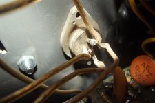
Also here are better pictures of the component and where it is attached to on the board There are 4 wires and four leads on the component. One wire is attached to each lead.

4 Wires On Component.jpg

4 Wires On Board From Silver Round Component.jpg
 
Last edited:
Hi All;
K1atn, "" Also, what You are showing is, as near as I can tell a three wire Diode assembly" It actually has 4 wires not 3. "" OK, I could not tell from the Previous Photo..
If You have a scope, look at the output from the Diode.. And make sure that the Bridge Diode is truly working in full wave mode..
"" If the R4 you're talking about is resistor 4 then no, I don't think it is hooked up correctly. with the meter it shows a steady 4.6 ohms on the +18v line. "" It should not show anything to the +18 volt line R3, a 4.7K is for the +18 volt line..
(Edit), where you measured 4.7K to the +18 volt side, You are actually measuring R3, because You are on the Ground side of R4 and R3, most likely, so that should be OK, but only If the other side of R4 goes to the --18 volt line..
And just for fun, See, if that end of R4 where it seems to be connected to +18 volt side of things, is in the Wrong hole..
What Does the other end of R4 connect to, the one opposite of where You say is connected to the +18 volt line ??
According to the Schematic that I have, D8 and D10 are connected to C14 on the minus side, C15 and R4.. D7 and D9 go the the plus side of C14 and the other side of C15 and the other end of R4, so they Should all be in Parallel.. Make sure that R4 is in the correct holes for it to be in parallel, with the Diodes and the Caps..
"" When i put my leads on R4 and the -18v line it starts really low and just keeps climbing. "" That is because of the Capacitor, which is charging itself from the voltage of the meter, used to check the resistance of the Resistor.. To keep that from climbing, the Capacitors need to be disconnected from the Resistor.. For, now You need not worry about it..
Just make sure that from one end of R4 it has a direct connection to D8 and D10 and the other end of R4 has a direct connection to D7 and D9, and the same with the two caps..
Also, look at this with a scope and see what kind of an output You have..

THANK YOU Marty
 
Last edited:
Interesting. This whole post may sound stupid because certain things have to have a other end to them, but I'm REALLY puzzled now!! What i AM sure of, is that R4 does NOT have a connection with D8, D10, D7, or D9 and i AM sure that One side of R4 is going to D5, and D6, what i can't seem to find is where the other end goes. It seems to go nowhere, i can't find anywhere that is making contact with the other side of R4??? as for D8, D10, D7, and D9 making contact with C14 and C15 they don't, and i can't find where they do. Granted i don't have very good soldering skills, but unless i'm just not making good enough contact, then what i just said above is all i have to report, in which case I have no clue what to do. It was my dad's Altair, and he may have modified it I know that when i got it it was gutted and all it had in it was 4 s-100 slots, the transformers, the PS board (already missing capacitor C12 which still has yet to be replaced) the front panel, and the case. I ALSO know that he swapped the original 8080 cpu board for a z80 cpu board back in the 80's, and he had several other boards in it. Unfortunately like i said, it was gutted and the boards that were in it have yet to be found. I bought a Z80 cpu board and a 4k dynamic ram board for it. I also had to solder wires to it and follow the diagram from the PS board and terminal block pages of the assembly manual to get it to even turn on. The outputs on the oscilloscope will be uploaded soon.
 
The videos for what i did with the oscilloscope are on my YouTube page, too many to put in one post the site says. there are 7 in all.

[video]https://www.youtube.com/channel/UCpIt2nT1CeQsHnjGQkss1Hw[/video]
 
Hi All;
K1atn, "" What i AM sure of, is that R4 does NOT have a connection with D8, D10, D7, or D9 and i AM sure that One side of R4 is going to D5, and D6, what i can't seem to find is where the other end goes."" ARE YOU sure that You are Checking R4, That sounds like R3..
"" It seems to go nowhere, i can't find anywhere that is making contact with the other side of R4??? as for D8, D10, D7, and D9 making contact with C14 and C15 they don't, and i can't find where they do. "" What I would suggest is either Take the Power Supply Board out and Trace out the Foil Paths or Turn the Power Supply Board over and Trace out the Foil Paths..
Most likely, the Old Rosin Core solder was not totally cleaned and so You are not making good contact and/or there is corrosion on the Leads and so you are not making good contact, to take a good reading with Your meter..
"" Granted i don't have very good soldering skills, but unless i'm just not making good enough contact, then what i just said above is all i have to report, in which case I have no clue what to do. ""
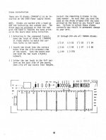
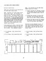
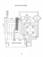
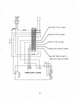
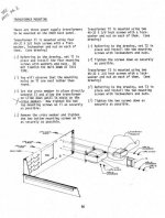
The other thing to do is to look at the Placement of the Various Parts starting on page 47 of the Power Supply part of the manual, and make sure by following from that page, that each part is in the correct holes and making connection and in the correct direction.. If need be take ALL of the Parts out, and Do it as though it were a new build.. Starting at page 47 and going to page 62, and check that You have the Transformers wired as shown on page 62.. That would be the first place to start, make sure that all of the Transformers are wired as shown.. Then check each section the +8 Volts, then the +18 volts and finally the --18 volts sections.. If need be Draw out Your own schematic and compare it to the one shown by Altair..
It almost sounds like, You have the +18 and the --18 volts mixed up, or else the Diodes are in the Wrong Direction, and so the Voltages are Reversed !!
Also, which Transformer did You Replace, From our talks, I had kind of assumed that it was for the --18 volt section, which I might be Wrong about.. And it could have been the +18 volt section and if that is the case, then Maybe You need to Replace the other Transformer as well..
What voltages are You getting out of the Transformers ?? Maybe that is where we need to start..
You had stated that alot of things were missing When You first "Found" this Altair, So, I would assume that Nothing may be right/correct and go on from there.. Everything needs to be Checked out against the Schematic..
I think at present the Best thing for You to do, is to Treat or Act as if You just got this Machine, and forget what You have done in the Past with and to it.. Start from Scratch..
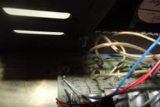
I Just got out my Step by Step System, (see pictures below..) which has been put away for a couple of Years or so.. And even though I have plenty of Documentation and there are Plenty of wires..
I have to start from scratch and take out ALL of the wires and make NO assumptions about How I think I have it wired.. I have to Treat it, as though I Just got it.. And Rewire it, and check out each piece and make no assumptions.. And assume that I have it wired correctly/right and even IF I trace out every connection, I still could have a mistake in the wiring that no matter how much I think I have checked it, I won't/can't find it, since I am blind to thinking that it is already correct..
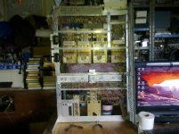
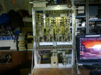
001.jpg 002.jpg

THANK YOU Marty
 
Last edited:
I followed the manual for putting the components in, and i AM sure i was measuring R4 because it was printed R4 right above it on the board itself.

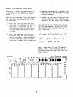
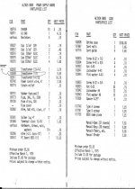
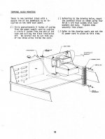
These are the pages i followed step by step for doing everything i did when putting the Altair back together and hooking it up.

p1.jpg

p2.jpg

p3.jpg

p4.jpg

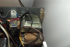
And this is the transformer i replaced

p5A.jpg
 
Hi All;
K1atn, "" I followed the manual for putting the components in, and i AM sure i was measuring R4 because it was printed R4 right above it on the board itself. "" OK ..

""These are the pages i followed step by step for doing everything i did when putting the Altair back together and hooking it up. "" OK..

"" And this is the transformer i replaced "" I still don't know if that is T1 or T2 or T3, and which voltage it serves..
Also, check to make sure that All of Your Diodes are OK, and doing as a Diode should, passing current only one way..
I may have to hook up my Transformers and take some Voltage checks to compare to what You are showing, If Your Diodes are ALL OK..

THANK YOU Marty
 
Yep!! the diodes all check out ok :)

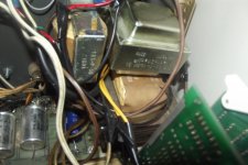
Here are a couple pictures of the transformers. the shiny silver one that says Radio shack is the new one i replaced the old one with. They are in the exact same formation as shown in the assembly manual in way of mounting so i do believe i replaced T2. I replaced T2 with one that says PRI. 120v 60HZ, and on the other side as seen in picture SEC. 12.6v -0- 12.6v 2A
Pic 1A.jpg

Pic 2A.jpg

DSCF2213.jpg

DSCF2215.jpg
 
Last edited:
Hi All;
K1atn, I am not feeling well, so it might be awhile, before I can Rewire the Altair and check the voltages.. Just to let You know..

THANK YOU Marty
 
Back
Top