• Please review our updated Terms and Rules here

Altair 8800 with Z80 CPU wont toggle anything. Help!!

Hi All;
K1Atn, for now assuming that You do indeed have the Eprom disabled, then having the Eprom in or out would make No difference..
So I would concentrate on looking at the Signals, on the Z-80 and on the Buss that have to do with Reading and Writing to the Memory.. Start from the the Memory Board and Look at the RD and WR signals tracing them back to the Z-80.. If they look the same, then You have a problem..
Also, check to see that You Aren't fighting Yourself, that the MWRT coming off of the Z80 Board is turned off or dis-connect from the Buss, since You are using You Front Panel for these signals and Not the Z-80, since at this point You are not using the Eprom for a Software Monitor to replace the lights and switches of the Front Panel..
Let us know what You find..

THANK YOU Marty
 
Hi All;
K1Atn, Thank You for the Link, I am Reading thru it and will let You know what or If I find anything..
It mentions the Phantom Line, Since the origional Altair Didn't have a Phantom line, I would for Now at Least until You can get more of Your system running with the Front Panel, Turn it off or dis-connect it from the Buss.. It could be turning off Your Memory or disabling it..

THANK YOU Marty
 
Hi All;
K1Atn, I would dis-connect or dis-able W26 thru W30, as well..
Also, IF I can get the PDF pages of the Monitor to copy to Notepad and then Assemble them, Possibly I can Program a 2716 for You.. It mostly depends on, If my SSM PB-1 will work anymore and If I can get a file made that I don't have to enter Manually.. I Just tried to copy to notepad.. Too many errors and too much missing.. So I will try some other things..

THANK YOU Marty
 
Last edited:
Hi All;
K1Atn, Thank You for the link for the .Bin file..
The Listing for the Moss 2.2 Monitor is in the Manual that you listed earlier, about page 75 and up..
Please give me some time and I will see what I can do..
I can Immediately Send You a 2732, Loaded as a 2716, in the lower addresses.. And What You have to do is Bend Pin 21 out and Tie it to Ground, ( with a wire wrap wire) instead of +5 which is what the socket has it tied to.. Then the 2732 should work as a 2716, and You should be good to Go.. If You want to go that Route..

THANK YOU Marty
 
sure we can go that route, so instead of putting pin 21 into the socket on the CPU board with the rest of the pins, i just solder a wire to it and ground it to any ground source... say ground it to the chassis or tie it to ground on the buss?
 
Hi All;
K1Atn, tie the Ground to another Ic on the Z-80 Board OR to the Ground Pin on the 2732, (I think pin 12)..
I will Send You a Personal Message here on the Forum..

THANK YOU Marty
 
I've forgotten which instructions are used by the front
panel to run but for the addressing for looking at an address,
it used the JMP instruction C3. It uses another instruction
for looking at that location ( as I recall ).
These instruction are sent to the Z80 over the data lines,
while the back plane data bus should be isolated from the Z80
and observed and controlled from the front panel.
The C3 is usually driven from a number of open collector
inverters ( or buffers ).
It is quite common for one or more of these to fail to drive
the Z80's data bus. or one of the address bytes to fail to
get to the Z80.
Use a scope or logic analyzer to observer the data pins
at the Z80 when you select an address to observe.
you should see the sequence C3 <LowAddr> <HiAddr>
on the Z80 data lines.
That will cause the Z80 to send the address onto the back
plane address lines.
Dwight
 
so to get this right, i use the ocilliscope and put it on the data lines D0-D7 on my CPU board while the front panel is hooked up to it and i observe what happens on each pin as i try to observe an address?
 
Marty, what do you mean by disconnecting W26-W30, do you mean disconnecting the wires coming from pins 26-30 on the buss as shown in the bus wiring diagram? and Chuck(G), I do indeed have the theory of operation manual as well as the operation manual, and Assembly/construction manual and Assembly hints for Mits Kits. They have been very helpful in me putting a half destroyed (meaning mostly and carelessly taken apart by me when i was 10 and the original boards are god knows where) Altair back together again. It's funny how you can grow up in your teenage years and suddenly learn to appreciate vintage electronics. Especially after my dad told me that the Altair had a major impact on micro-computing.
 
Okay, i did a few things. I measured the voltages on each data pin and they came out as follows... D7-5v, D6-1.1mv, D5-1.1mv, D4-1.1mv, D3-1.1mv, D2-1.1mv, D1-1.1mv, and D0-5v. I also measured the voltage of A0 on the bus as i tried to go to that address and in doing so found something interesting that made me test a couple of other switches with it. my dad said that when A0 is switched to on and examine is toggled it should put voltage on the bus and when examine is depressed the voltage should go down to zero. well here's what i found out. When i put the voltmeter on pin 79 (A0) there was no voltage, when i hit reset it showed 3.47v on that pin and when reset was depressed the voltage was again zero. I then switched A0 on and hit examine... the voltage went to 3.47v and stayed there even after the examine switch was depressed. It did this even when A0 was in the off position and i hit examine. Any input on this would be helpful.
 
Last edited:
Hi All;
K1Atn, "" Marty, what do you mean by disconnecting W26-W30, do you mean disconnecting the wires coming from pins 26-30 on the buss as shown in the bus wiring diagram? ""
No, As shown in the Manual for the Z-80 CPU Board, these are the Jumpers for connecting and dis-connecting from the Buss, 5 signals that might interfere with the operation of the Front Panel.. Just like You did with the Phantom Enable, see page 90 of the Manual..
"" When i put the voltmeter on pin 79 (A0) there was no voltage, when i hit reset it showed 3.47v on that pin and when reset was depressed the voltage was again zero. I then switched A0 on and hit examine... the voltage went to 3.47v and stayed there even after the examine switch was depressed. It did this even when A0 was in the off position and i hit examine. Any input on this would be helpful. ""
Actually, this may be correct, for after you hit "Examine" any switch in the One position would show a High 3.47 volts there on its pin and hopefully on the Leds as well, since that is the address that You are examining and at this point see random data in the Data lights..
And now changing the Switches, so that if You would Press Examine again it puts what ever switches you have set in the "one" or up position and they are now being Examined..
I am a little unclear here about your response ""It did this even when A0 was in the off position and i hit examine. "" If having switched off A0 and Pressing Examine and A0 stays high 3.47 volts, then that is Wrong.. But, If A0 is on when pressing Examine and A0 buss pin (79) and the Led shows it being on and then pushing A0 to the off position, Without pressing Examine, then that is Correct, A0 should stay on..
But, If You change the Switches After pressing Examine, and instead Press "Deposit" then instead of another Address, You are changing the Data and the Data Leds should match Your first 8 switch positions.. Remember, that the Switches are for Both Address and Data, depending on whether you Press Examine or Deposit.. I hope this Helps..

THANK YOU Marty
 
Last edited:
Hi All;
K1Atn, On another note, since You are poking around with Volt meter and oscilloscope leads.. And accidents can and do happen..
I would Very Strongly suggest that you do the following, as soon as You are able.. More about Able in a bit..
Disconnect the power leads to all of the Power Transformers and tape them up.. Leave all of the Transformers in the machine along with the Rest of the Origional Power Supply, and Then Mount a pair of Modern Switcher Power Supplies.. I will find the numbers that you would need, for these Switching Power Supplies..
Now for the Reasons !!!
As, stated way back at the beginning of these postings, the Capacitors, are about 40 some Years old, Old Caps do Not age very well.. They tend to Leak, Crack, Open and Short Out.. The Leaking and the Shorting out are what can do the most damage to Your Machine.. Also, since the origional Power Supply is Linear, it will keep on feeding voltage and Especially Amperage to what ever it is attached to.. Even a Short, like from Your Volt Meter Test Leads..
Whereas a Modern Switcher will automatically switch itself off when Presented with a short.. And save an IC, a Board full of Ic's Or the whole computer, before the machine can be turned off.. With the old supply it would have just kept on supplying power.. I know what can Happen, I've done it many Years ago, on an old Altair 8800b that I bought New.. A solder ball fell off of a board that I was repairing and shorted the 18 volt line to a 5 volt line and took every board out, before I could turn off the machine..
Also, the Switcher supplies provide a Cleaner voltage, Your Regulators will run cooler and provide a more stable voltage to the Various boards.. And You can switch it back to the origional Power Supply for when You want to take it to a show or something like that, and remove the Switchers..
But for Daily use and when poking around I would sure suggest using these switchers..
Now about Able, Since I don't know Your situation, I would see if Your Parents can Help You get these Switcher Power supplies, and then you could work something out with then, to pay all or part of the money back thru your allowance or thru Odd Jobs You could do around the House or in the Neighborhood..
The Power supplies that You would need to get are something like the following ::
One would be something like a MeanWell SP-150-7.5 OR a S-100F-7.5..
The Other Supply would be a MeanWell T-40C OR a T-60C..
These Power Supplies can be obtained from Digikey, Jameco, Mouser, etc..
If You go to Grant Stockly's site, there are instructions for wiring up these Supplies.. And I can be of help also..

http://www.altairkit.com

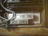
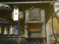
Here are some Pictures of my Altair wired with these supplies, and the Transformer wires taped off::

001.jpg 002.jpg

THANK YOU Marty
 
Last edited:
OK I'll get on that, I'm 23 now so i have my own money i just have to have enough to get the power supplies because i don't have a job yet. the SP-150-7.5 and the S-100F-7.5 are a little hard for me to find at least for a good price and in stock. Will a SP-100-7.5 do? Also when replacing the caps on the power supply board, the 6 silver 3300mfd caps say Arcolytic on them but the assembly manual says they're electrolytic. So now i need to know if i replace them with electrolytic 3300mfd capacitors or Arcolytic 3300mfd capacitors.
 
Last edited:
Same thing, really, Arcolytic is just a trade brand of aluminum electrolytic.

As I mentioned, electrolytic capacitors of this age tend to dry out--they don't short, but they turn into what amounts to empty cans. That's why I asked you to use your o-scope to check for ripple on the PS output. Capacitors have also gotten a lot smaller over the years. If you're interested in preserving the appearance, you could open one of these old cans, discard the innards and stick a modern cap inside.

If you're looking for overvoltage/overcurrent protection, you can simply add a circuit to the output of your linear PS, rather than completely replace it. Linear supplies tend to have a much longer life (due to lower ESR heating on capacitors) than switchers.
 
Chuck (G), I just made a video showing what my scope shows when hooked up to each capacitor. I tested each capacitor before the video and they all showed the same thing. I left the scope on one capacitor for the video. Watch the red line because the blue one is CH1 on the scope and is not hooked up. The voltages in the video are from the scope it's just not in frame.

 
Last edited:
Back
Top