• Please review our updated Terms and Rules here

uPD765 FDD VCO sync generation

JonB

Veteran Member
Joined
Jan 26, 2014
Messages
1,652
Location
South Herefordshire, UK
An arcane question for you all.

I have a Philips P2000C with a broken floppy drive interface. It uses the NEC uPD765 FDC chip, and this has an output on pin 24 called VCO Sync. It is used to bracket the RDD pulses coming off the drive.

Now on mine, it is low all the time (it's supposed to go high before each read data pulse, then low after). However, I swapped the FDC into a known working machine that uses the same chip and proved it is working, so something else is not right with the P2000C.

My question is, how does the FDC generate VCO? What inputs does it use to synthesise the signal? I know it has a programmable delay (to wait for the heads to settle down after loading) before it kicks in, but mine is contestanly low and I can't see why.

Any ideas?
 
I'd start by looking at the INDEX input to the 765. The 765 pulls VCO SYNC low for 500-1000 usec (depending on 765 version) when it receives the INDEX pulse.
 
Hi Chuck, how are you? :)


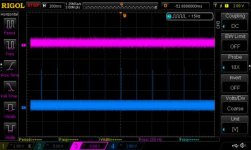
There is an index pulse. Here it is (in blue) with the VCO sync in magenta, above.

DS1Z_QuickPrint6.jpg

As you can see, vertical scale for Sync is 5v, and for Index 2v. So VCO is doing nothing...
 
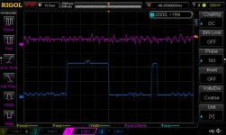
Close up of the index pulse (single spike in previous picture). It is actually two pulses. Is that normal? The drive is proven working (with 22DSK144.EXE and the drive connected to my old PC, it can read the P2000C's disks).

DS1Z_QuickPrint7.jpg

The wide pulse is 30uS and the narrow pulse is 5uS. But each set of pulses is 200mS apart which is correct for a 300 RPM drive (300 RPM / 60 seconds = 5 RPS; 1 sec / 5 = 200Ms).
 
Last edited:
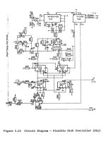
The machine uses a PLL with a VCO for timing and data separation, So far the only problem I can see id the missing VCO Sync which is going to be fatal as it is used to "switch on" the PLL for data acquisition. However, this circuit is kind of clever, because it maintains a 250khz feedback signal when there is no read data so that the VCO doesn't drift between reads. And it says that the VCO sync actually switches the signal over between the 250Khz signal and the read data.

The PLL looks like this

p2000c PLL.jpg

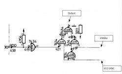
..and taking a closer look at the 74LS00 gate array at the bottom left, you can see how VCO Sync switches (incidentally, that line coming to pin 5 of the 74LS00 is the 250Khz feedback signal).

RDD input annotated.JPG

Edit: Urgh, gawd, this forum software is compressing the images. How to disable?
 
Are you certain that nothing other than the 765 is driving the VCO SYNC/WINDOW pin? Easy enough to determine, I'd say.

Not all circuits actually use the signal, however. For example, if your data separator is like a WD9216 digital separator, there's nothing to sync.

But getting back to the matter at hand, silly observation: you do understand that you have to be executing a read or write for the VCO sync to do anything, don't you? Basically VCO SYNC goes high when the controller is searching for the start of the address or data fields--and the intention is to allow your PLL to lock on the bitstream coming from the floppy during a data transfer, while being "blind" to the garbage due to write splices. So, the VCO SYNC goes active when the start of an address ID header is found during read or write and when a DAM is found during a read, but not a write. During, say, a format operation, it stays low, because there's nothing to look for. Similarly, if the 765 is idle, VCO SYNC will stay low.
 
Well, the schematic says that Sync is connected directly to the bottom of that NAND gate. I have checked it, but only for continuity and shorts. I'll take another look. The FDC is socketed so I was thinking of bending the pin to isolate it from the board, then taking measurements, but I don't want to damage it.

Good point about SYNC and reads - I knew about it. All those scope measurements were taken while it was attempting to read. The machine has a monitor that allows you to test read/write continuously, which is handy when doing this sort of thing. I was expecting to see something happen on Sync at the point of issuing a read but like I say, there is nothing. That noise is there irrespective of read or idle state.
 
Last edited:
Since VCO Sync is an output and it is always low, perhaps there's simply a short to ground either in the PC2000C wiring or in the NAND gate. Just a suggestion...

cheers,
Jeff
 
Good idea sergey, I should have thought of that!

Anyway.. I bent the pin and applied a probe to it. Still getting a bunch of low voltage (200mv peak to peak) noise when reading from the disk, even though it is isolated from the board. There is a slight reaction as before, but no clear signal.

This is weird.
 
The other test machine isn't a P2000C, it's an Amstrad CPC6128.

I did think of doing that, so that I know what it should look like. Since I am on holiday next week, I will have more time to investigate it. Are there any other suggestions I might try? I reckon I should scope every pin on the FDC, although I don't know how to tell if a trace is right or not (given that there is no Sync, other signals may be affected).
 
Have you placed a pulse sniffer (logic probe that extends the length of a pulse to be visible) on the pin to see if you're just missing a few microseconds in a sea of milliseconds?
 
I don't have one, but I can set the scope to trigger on a pulse. Since it is a DSO, I can see what it records and sort of go back in time. There is no pulse whatsoever on the Sync pin...
 
Back
Top