• Please review our updated Terms and Rules here

Pettester rom in a 2001 chicklet

Joined
Dec 4, 2014
Messages
11
Location
Birmingham, United Kingdom, United Kingdom
2316 & 2114 combo, 447 series basic 1 roms. Which socket do I put the pet tester in?

I have a full set of good roms, 3 were faulty so replaced with 2716, oddly enough 4, 6 and 7.

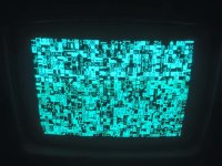
Don't have any ram to see if any are bad or not but I get garbage on the screen, all proper pet characters however it's always the same characters each time, no matter what I do it's always the same display...

Regards

Courtney x
 
So, for a Chicklet PET you'll specifically want the "2k" version. (There are several versions floating around; the original version I wrote for "Dynamic Board" PETs that fits on a 4k EPROM like a 2532, a hacked version of that that includes CRTC initialization code for Universal Boards, and 2K variants that fit on 2716s, etc. It is the same code, just ORG'ed at F800 instead of F000 and the jump vector in the top few bytes set accordingly.) Just burn the apropos one and stick it in the "highest" socket.

It IS a little odd the characters are always the same between power cycles... it does look "random" with no discernable repeating pattern?
 
It was a 2k one I believe that I used, it didn't take the whole of the rom space.

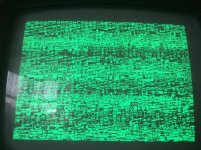
12106723_887427331306532_8580314572174018359_n.jpg

This is a screen shot, it's always the same no matter what I do with it, unless I take out the character rom.

I have a second PET, also a chicklet but with a 32k basic 4 board in with the TO3 cased voltage regs, even though the model on the back states 2001-8N so of course I can't swap anything.

I have tried another 6502 and that makes no difference either.

I am currently charging my scope so I can have a nosey around the clock and reset pins but I need to find some 2114's to piggy back the video ram for starters..

Unfortunately all the ram on this board is soldered :-(

Courtney x
 
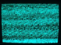
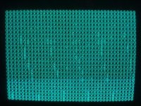
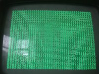
image.jpgimage.jpg

Ok.

More progress, I finally got the PetTester to work, but, if I put the 6520 in that's closes to the ram or remove the 6520 by the IEEE port then the tester won't work. It just comes up with the same picture as previous.

Also if I put any of the OS Roms back in while the PetTester is in it also does the same screen as my last post.

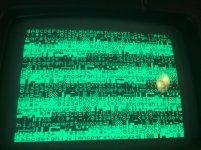
The pics from the PetTester are here but the video is much more interesting.
 

Now the interesting thing with this is :-

When I first turn it on I get garbage on the ram test screen, second Ram test screen comes up all B's, each time it tests the ram there are more G's and less B's.

This is so confusing.

All 4 volts rails are between 4.95 and 5.03.

While it was running the test I turned it off and on again and then I got the same garbage screen taht I had back in my 2nd post and can't get the test to run again.

Starting to think ROM/CPU sockets to start with.

Only socketed chips in place at the moment are :

2716 in H4 - PetTester 2k
6502 - CPU
6522 - VIA
Character Rom -08 in A2 (A3?)
6520 - PIA in B8

If I put the PIA also in G2 then the test rom wont run and I get the same (exactly the same) image as in my second post. Either PIA works for the test in B8.

Obviously the clock and reset are running so what am I looking for next?

I still need to get some 2114's as I don't have any but I am thinking of changing all the rom sockets first.

Courtney
 
When I first turn it on I get garbage on the ram test screen, second Ram test screen comes up all B's, each time it tests the ram there are more G's and less B's.

Well, a flash of a garbage screen when you *first* turn the system on is normal. (Well, at least if the monitor is semi-warmed up.) The delay on the 555 reset circuit seems to range between a second or two so if your monitor comes on fast enough you'll see the initial power-up garbage for a moment before the code executes. But it is really odd that your RAM gets "better" the longer it runs...

All 4 volts rails are between 4.95 and 5.03.

I was going to ask if you'd checked that before I read your post more carefully and saw you already had. Weird...

While it was running the test I turned it off and on again and then I got the same garbage screen taht I had back in my 2nd post and can't get the test to run again.

Hrm. Check the RESET circuitry? I had a capacitor go bad on the board I was working on and prevent the system from starting most of the time; if you power cycled it enough times it might randomly go for a little only to then halt again a short time later. Check the RES signal on Pin 40 of the 6502 while powering on and see if it's stable at a reasonable TTL high value after initially going low for a second or two.

If I put the PIA also in G2 then the test rom wont run and I get the same (exactly the same) image as in my second post. Either PIA works for the test in B8.

The RESET line does go to all the I/O chips, if your reset circuitry isn't reliably going high maybe more load makes it less likely to do so? (Utter shot in the dark.)

I have to admit what I find a little weird is why your screen has all the hash on it while it's showing the character set part of the test but is clean while showing the B/Gs. I'm looking at the code I banged out and it looks like the delay loops for both the charset display and the memory test are the same. Here's what the code looks like for the charset portion:

Code:
charset:
 txa
 sta $8000, x
 sta $8100, x
 sta $8200, x
 sta $8300, x
 inx
 cpx #255
 beq endcharset
 jmp charset
endcharset:
 ldx #0
 ldy #0
 lda #0
 jmp delayloopin2

delayloopin2:
 lda $0000, x
 inx
 cpx #255
 beq delayloopout2
 jmp delayloopin2
delayloopout2:
 iny
 cpy #255
 beq enddelay2  
 jmp delayloopin2
enddelay2:
 ldx #0
 ldy #0
 lda #0
 jmp restartprog

(I apologize to everyone out there who's a way better 6502 coder than I, this was the first 6502 assembly I ever wrote *and* I was working with the constraint that I couldn't trust any RAM to work so everything runs from ROM and the CPU's three not-really-interchangeable registers.) The "write the charset" portion is easy enough to understand, starting with X=0 it loads x into the accumulator, writes the accumulator to four addresses spaced 256 memory locations apart in screen memory, increments X, and loops until X=255 at which point it jumps to the delay loop, which though headache-inducing logic writes X to the first 255 memory locations 255 times each to produce a human-scale delay before jumping back to run the memory test again. (And I'm seeing a bug where I should have put the CPX and BEQ before the INX, sigh...) The delay loop after the memory test is essentially the same (including the lda $0000,x) The "hash" you're seeing on your screen during the character set display makes it look to me like video RAM is being continually hit during the delay loop (since early static PETs have contention for video memory), but... A, that shouldn't be the case, and B, if there's some sort of crosstalk going on between $0000 and $8000, why is it only showing up for the one loop but not the other? Confused.

(Can someone else who's run PETTESTER in a Static RAM PET comment if they also see hash during the charset display delay loop?)
 
Strange. Again, I'd assume the noise was normal if the PETTESTER was running actual the character writing loop over and over again (My first thought was maybe I'd written it that way, which is why I pulled the source out to look at it), but unless one of the modified versions out there changed that that isn't the case. Perhaps there's something about the way video memory contention works on the plain 2001's I'm missing. (I seriously can't think of any reason why the B/G screen would be clean while the charset one isn't.)
 
Back
Top