• Please review our updated Terms and Rules here

pdp 11/34 - a little help, please.

roberttx

Veteran Member
Joined
Aug 6, 2015
Messages
1,133
Location
Texas
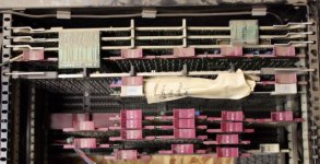
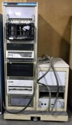
I think that I may have just bought a pdp 11/34. I don't know 100%, as we're out of town, but I was the high bidder and it sold for my max bid, so I'm confident that it's mine. It's in a rack and a half, with a dual 8" floppy drive, two or three units full of what I guess are Unibus cards and who knows what else. I'm guessing that the half rack on the right is the power supply.

Next week, I'll have two days to get it off site and there's no way that I can haul it intact, so I'm going to have to take it apart.

What tips do the assembled DEC experts have for me? Things I should watch out for, things to avoid, disassembly tips - all comments are welcome. Heck, I don't even know whether to bring Metric or Standard tools, at this point, so don't hold back for fear of insulting my intelligence. :D

Here's a pic - sorry it's just a screen grab, so you can't make out much detail.
dec1.jpg
 
1) I don't think there are any special rules for DEC kit. Been a while since I moved PDP-11's as part of my job, but I don't remember any special rules.

2) The key think is to document and label. You can't take enough pictures. Photograph everything in detail BEFORE you touch it. Card Order is important in PDP-11s, photograph and make notes of where any card you remove is. Label everything. Preferably with tie on labels. Nothing sticks well to old computers no matter how well you clean.

3) Things with moving parts such as hard disks and teletypes often have "transit bolts" or "transit plates" that hold heads in place. These are often lost, if so you can improvise but you need the manuals to see how to improvise. I can't see any in the photo so you may be able to ignore this. Hard disks may also have "head retractor" batteries that can leak, or capacitors that are dangerous when shorted.

4) Not sure about the floppies, but again floppy disk drives normally come with Transit Cards or Head Protector that stop the heads getting banged and damaged in transit. I can designs on the web for 5.25" but I think those are 8" drives in the machine. It may be worth improvising.

5) Take both sorts of tools. Modern tacks in the UK have metric bolts, apart from SUN Racks which have a US specific thread. However 1U (originally a post office unit) is still 1.75"....

best of luck
 
I don't see any DEC hard drives in the picture, so that will make moving simpler. DEC floppy drives are single sided, so you really don't need head protectors when moving them.

I agree with "take lots of pictures". Make sure that you have detailed pictures so you can get all of the cables back in the right place, and with the right orientation.

You can do your initial debugging with just the processor chassis, but you will need to move the Unibus terminator from the last chassis in the chain, to the last slot in the processor chassis.
 
A few more suggestions....

1) While many of the cables have keys or markings that are meant to ensure proper orientation, they may be hard to see, taped with adhesive that won't last or are faded. Don't hesitate to mark both cable and receptacle if the cable has the appearance of being reversible and/or the markings unclear. For cables that plug directly into the unibus, while they have key, that won't prevent you from partial insertion. So consider marking these as well.

2) I used to take a thin piece of cardboard shaped like an 8in Floppy and insert these in the RX02 Drives for shipment. Just match the size and spindle hole. Don't use a floppy itself for this, even one you intend to sacrifice. While these are single headed drives, the felt on other side is probably not in good shape.

3) We use to leave the boards in the PDP 11/34 when I shipped them. We took a large 1-2 inch thick foam sheet and cut it to match the chassis cover. Lay it over the tops of the cards and secure the cover. This prevents the cards from rattling in the chassis.

4) The 11/34 chassis typically has slides that allow the chassis to rotate. If you leave the chassis in the rack, bolt the chassis directly to the frame. Otherwise it will shake during shipment (don't remove the slides).

5) Be wary of anything that is the original foam. This stuff will shed or decompose during transit and leave debris or sticky bits all over things that will be hard to clean. Wrap or isolate it if possible.

Good luck,
Jerry
 
Take a friend! I have a couple 11/34 systems and know first hand they are well over 100 pounds. Everything everyone said is good but did not see if anyone warned you about how heavy that stuff will be. It’s definitely a two man job.
 
I would second QBUS's suggestions. Two people are really useful.

Can I also say make sure its well secured in whatever vehicle you use to move it. I would look at getting some really good webbing straps and making sure you have something solid to retrain things too. Might be worth driving slowly as well :-(
 
Thanks folks, all useful stuff.

I got a look at it in the flesh this morning (before having to hare off to fix a snafu on the part of my CPA). If the power cord is any guide, I don't think that I have the power to run it all, so complete reassembly is unlikely. That's not necessarily a bad thing, as I don't have space for the giant rack in any case. I might be able to get away with powering up parts of it - I'll know more when I've gotten into it a bit further.
 
It's probably a "whatever's convenient" power feed into a distribution box, so the individual bits of the system are probably running on regular 120 VAC single phase. Bringing up the main 11/34 chassis and RX02 drives on a regular house branch circuit should be no problem.

Looks like you have a lot of I/O interface gear with it. If there's no software/documentation with it, you'll be reverse engineering it if you want to use it, most likely. The good news is, while it's interesting stuff, it's probably not that useful to you w.r.t. exploring PDP-11 architecture.
 
I've run an 11/34a, RX02 and two RK05's on an single 15 AMP 120 Volt Circuit. If there's an H861 power controller in the rack, its probably wired for a 30 amp circuit.

The following is a pretty good guide to the options and power requirements - ftp://bitsavers.informatik.uni-stuttgart.de/pdf/dec/pdp11/1134/1134_UsersManual.pdf

Leave yourself a margin for safety, no extension or frayed cords, have healthly house writing, don't share the circuit then you should be able to run the basics.
 
Well, I'm going to be in pain tomorrow!

The good news is, those who said it was likely a power distro were right. Once you got past it, everything was running off bog standard 110V, 15A.

The bad news is, the battery on my camera went flat, the mess of cables made spaghetti look like parallel lines and, under pressure of time, I abandoned all hope of recording what went where and just tried to save what I could.

As well as the RX02 FDD, I have one rack with PSU & control panel and two racks with PSUs. All appear to be Unibus and the one that I looked underneath of was wire wrapped. I also saved the rails, a filter/cover for a rack, the cables (I did keep the FDD cable separate, so can ID that) and some other bits and pieces, like some rack mount fan units.

I feel a bit bad about not doing a better job of documenting it (or, indeed, any job!) but I was the only bidder so better that I saved what I did than it all go to scrap.

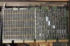
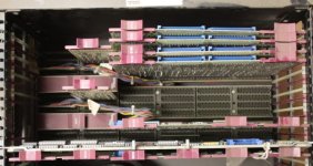
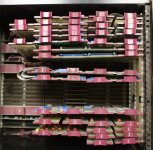
I have a list of all the cards, which I'll try to type up in the next couple of days. For now, here's some pics that I got once I'd manhandled the first load into my workshop.

dec2.jpg

dec3.jpg

dec4.jpg

dec5.jpg
 
Don't feel too bad about it -- even though I've documented all of the PDP-11 hardware I've worked on, I've always ended up reconfiguring it as part of the clean-up/repair anyway.
 
I would not worry about how it’s configured at this point anyway. The mainframe will have a sticker on it that shows the location of any of the important things like the CPU cards, control panel interface and location for the bootstrap and the terminator. I would start by removing everything and cleaning and then just install the CPU cards, control panel and bootstrap along with one memory and one DL11 communications card and the terminator along with a bunch of jumper cards. Get the thing running using just the front control panel first and be able to load, read and run loops to see if the processor is up and running correctly. Then maybe just work with the RX controller card and get it to boot RT-11 from disk. The big issue will be if you have enough grant cards. They appear on EBay quite often and you don’t need full size cards just the little jumper ones. The other issue you are going to run into is the NPG circuit that runs under the frame from card to card and where it’s cut and may need to be jumper that involves access to the underside of the system. A real challenge when not rack mounted. It looks like that system also had an expansion chassis and that may be a great source of jumper cards if that’s the case. All of this may sound like a bit much but get the PDP-11/34 System User Manual (EK-11034-001) and that will explain all. By the time you’re finished with this project you will be a Unibus expert! The 34 is a great system being easy to work on and way less stuff in it then the higher series systems, my 34 is set up with dual RL drives and I don’t use it near as much as my Qbus systems but still it gets you in the world of Unibus and if you’re going to be a PDP-11 person you’re not big league until you have a Unibus system.
 
Thanks, chaps. I had to look up grant cards, but I have a total of 9 (only two in the "main" chassis, though).

This afternoon, when I should have been working, I went through all the cards and typed them up. I think that I've, if not identified, at least found a description for most of them. The two that I couldn't ID were the M6864 and the one pictured earlier in the thread, which says "703536-100P" on the board, with nothing on the pulls. Also, is the one marked "CMD" a SCSI controller?

Anyway, in the "main" unit with the control panel, I have:

Card Qty
703536-100P 1
CMD 1
M105 2
M1500 1
M1501 5
M1502 3
M7821 1
M7856 1
M7859 1
M8265 1
M8266 1
M8267 1
M920 1
M9312 1

In the next box, there's:

Card Qty
M105 2
M1801 4
M7521-AA 1
M7856 1
M8256 1
M920 2
M9302 1

And in the final box (with the six grant cards) there's:

Card Qty
M105 3
M1500 2
M1501 4
M1502 4
M1801 2
M5864 3
M6864 1
M6865 1
M7212 3
M7213 1
M7248 1
M7821 2
M783 1
M784 1
M785 4
M7864 1
M7865 1
M920 3

I haven't yet examined any of them in detail (my googling thus far suggested that I might want to see if the RS232 cards are opt YA, for example). The I/O cards suggest that it was sampling something, but what else can y'all make of these lists?
 
For completeness, here's what I think the cards are, based on some googling:

703536-100P ?
CMD SCSI Controller?
M105 Device / Address Selector [ PDP-11]
M1500 Bidirectional bus interfacing gates [pdp8/pdp11]
M1501 Bus input interface (16 drivers)
M1502 16-bit bus output interface
M1801 16-bit reed relay output interface
M5864 Opto-isolated Input
M6864 ?
M6865 Opto-Isolated Output
M7212 Address line bus repeater control for DB11
M7213 Bus repeater control, for DB11
M7248 Unibus repeater BBSY
M7521-AA UNIBUS to ethernet adapter (I have a small panel that I think goes with this)
M7821 Fast M7820 Interrupt control, 7-bits, 1 per PDP11 peripheral
M783 Bus transmitters 12 drivers, mixed logic
M784 Bus receiver (16 receivers), single in/single out
M785 Bus transceiver, 8 drivers/8 receivers (8-bit)
M7856 RS-232 SLU & realtime clock option (not sure if YA or not)
M7859 Console interface; programmer's console (11/34a)
M7864 DR11-L, 2 word unibus input interface
M7865 DR11-M Two word unibus output interface
M8256 RX02 floppy disk controller
M8265 11/34A data paths module (Replaces M7265)
M8266 11/34A control module (Replaces M7266)
M8267 11/34A floating point processor
M920 UNIBUS connector
M9302 11/04 UNIBUS terminator, far end
M9312 Bootstrap terminator with 5 empty ROM sockets; one for CPU diagnostics, 4 for peripheral boots
 
Sounds like you got everything there to build a nice little unibus system, if there is such a thing. The DL-11W (M7856) is the card that you will want to use to communicate to the system and serve as the con. There are jumpers and stuff that will have to be set up first but the DL-11 manual explains that. There should be some memory cards next to the two CPU cards and FPU, they are the only other cards that use all six slots. With the FPU and the M8265/66 cards you have a 34B. The best thing to do now is download the PDP-11/34 System User Manual and start reading that. When you get to the point of completing basic testing and have the RX-02 wired up let me know and I can mail you a RT-11 disk just be cautious first in getting everything together and when you get to the drives you would be well served by cleaning and giving a drop of oil to the bearings on the AC drive motors on the disk drives because they have a tendency to freeze after years of not being used.
 
Thanks, Qbus, I'll keep you posted. As you noted, my not having a rack poses something of a challenge - I might have to keep an eye out for a half height one, though whether I'd find one heavy enough is another question...

My guess would be that the "mystery" card that I couldn't ID, marked 703536-100P, is the RAM card. It's the only other full length one and, while I haven't looked at the chip numbers, it certainly looks like banks of RAM.

Right now, I have three Unibus chassis, with power supplies and an RX02 covering the floor of one room of my 'shop. That's not counting the boxes full of cables, rails etc. that are filling up all the space in the cab of my truck. Clearly, some organization needs to be done, if I'm going to have space to do anything.

I can make some shelf space but, as noted, these suckers are heavy! Looking at the chassis, it seems that the front part, with the Unibus slots, etc. can be separated from the back part. As long as I label up the power connectors and make a note of where each one goes, is there any reason why I shouldn't separate them, to make it easier to get everything put on shelves and out from underfoot?

Supplementary question - would it do any harm to power them up first? I'm going to have to see if the PSUs fire up at some point, after all.
 
I would start with just the base system in the first chassis.
You could even removed the Floating Point for the first try.

M8265 11/34A data paths module (Replaces M7265)
M8266 11/34A control module (Replaces M7266)
M8267 11/34A floating point processor
M7859 Console interface; programmer's console (11/34a)
M9312 Bootstrap terminator with 5 empty ROM sockets; one for CPU diagnostics, 4 for peripheral boots
M9302 11/04 UNIBUS terminator, far end

Then add:
M920 UNIBUS connector
M8256 RX02 floppy disk controller

Then add:

CMD SCSI Controller?
M7521-AA UNIBUS to ethernet adapter (I have a small panel that I think goes with this)
M7856 RS-232 SLU & realtime clock option (not sure if YA or not)
 
" As you noted, my not having a rack poses something of a challenge - I might have to keep an eye out for a half height one, though whether I'd find one heavy enough is another question..."

If you can't buy, beg, borrow, or steal a rack, it is possible for someone with basic handyman skills and tools to make one. There are examples on the web although most of them seem to be focused on racking audio gear. The only tricky part might be the spacing of the holes in the actual mounting rails. You can finesse that part by buying them ready made. I got a 22U set from Raxxess. Just make sure that you allow for the fact that this old gear is heavy. If you have any components that slide out for access you would be wise to have them near the bottom of the stack and have something like slide out feet that prevent the whole works from tipping over when say you have an RL02 slid out to change a pack. Securing the top against a wall or securing all four corners to the floor would also be prudent.

Having a full rack tip over would ruin your day even if it doesn't end up on top of you or someone else.
 
A full size PDP-11/34 weighs in at around 110 Lbs. (50Kg) with no cards installed. You will need to get to the bottom of the system to check NPG chain and not having the system in a good equipment rack may be an issue. The rack will also have to have both front and back rails to support the rail system that the computer is installed on. The advantage of the rack is that you can slide the system out to work with the cards and by using the rail system they came with you can slide out, pull the lever and the whole system will pivot around to expose the underside. Not given much thought to it before but that may be my next YouTube Video is showing how the slide rails work. Have one on my 23 with the CDC tape drive showing how that rack stuff works.
https://www.youtube.com/watch?v=oWnjuLS6jxI
You can see my 34 system in the background. It may be a big hassle but your life will be better if you locate a small equipment rack with both front and back rails and on wheels. You will also run into some of the same issues dealing with the RX-02 drive being that wants to live in a rack also. Things like cleaning and racking everything up now will have huge payoffs later. The short rack that was next to the large rack looks like it would work for the 11/34 and the RX drive.
 
Well, the racks in my first picture are long gone, but a suitable one will turn up in due course. I noticed the clever tilting arrangement, giving access to the wire-wrap underside, while removing the chassis and made a point of saving the rails (all of them, including the parts that mount on the rack). So I'll be able to use them in the future.

Right now, though, I need to do something to give myself room to maneuver. I've downloaded the BA11 manual and it seems to confirm that it's possible to separate the PSU from the cage etc.

So, what would really help me today would be some advice on (a) any downsides to separating them like that and (b) whether it's safe to fire them up, briefly, before I do so.

Thanks.
 
Back
Top