• Please review our updated Terms and Rules here

SWTPC TVT2 Under Repair

Mine was the SWTPC KBD-2. I despised the thing for its lousy feel and lack of rollover.

Mine might be a 2.. I'll have to check it. It is almost comically uncomfortable to use. I still can't believe keyboards were ever so exotic or expensive that hobbyists rejoiced when something like that became available.
 
Keyboards were usually pretty plentiful on the surplus market at the time. I eventually adopted one of the black plastic molded ones used on several terminals. I think I still have the "HERE IS" keycap from it. The best ones were from George Risk--and you can see him mentioned in the Apple I construction plans. I had a GRI doozy from an RCA Spectrola system--each key was an individual sealed reed switch with ceramic magnets making up the spring. It had a very strange feel--and was EBCDIC-encoded.
 
Ok it looks like mine is a KBD-3.. at least, reading from the bottom side. So far only the N key works somewhat reliably. Continuity testing suggests some keys are permanently shorted, others come down in resistance as you press the key but not quite all the way to 0. I'm assuming this a key problem and nothing to do with the ICs.

Still not clear on the design of the switch. Looking at this broken one, it looks like two pieces of copper wire soldered into the PCB and then something inside the switch (unseen) connects?
 
Probably the wires are simple cross-connect springs. That would explain the shorting.

If this were my keyboard and I didn't care overly about "authenticity", I'd look into changing each switch out for a Cherry MX unit. Available on eBay, in lots. You get to select the keycaps, but those are easy.
 
Probably the wires are simple cross-connect springs. That would explain the shorting.

If this were my keyboard and I didn't care overly about "authenticity", I'd look into changing each switch out for a Cherry MX unit. Available on eBay, in lots. You get to select the keycaps, but those are easy.

Yeah it kind of puts me in a tough spot.. this is an important original example of hobbyist computing so I'm reluctant to deoriginalize it. The keyswicthes dont seem to be serviceable though.

I did note on a couple of keys I get the proper resistance readings.. but no character generated by the system. If I pound the keys a bunch of times I can get a bunch of keys working.. but then they stop again.
 
If you think you can get some into the innards of the switches, you could try squirting some contact cleaner into each switch and working it a bit. You might get most of the keys working.

The KBD 2 used little more than a bunch of diodes, a few transistors, and 2 RTL (!) hex inverters. So naturally, no fancy stuff--not even shift-lock.
 
I'm starting to think this is more than a simple keyswitch problem. I have two sets of original CT1024 boards. I've swapped in different RAM and cursor boards and get different results. When I swapped all my original boards back into the machine and turned it on, it kept randomly producing O characters. But as it was doing that, I could freely type almost any other key I wanted and it took it. I powered off and on.. again.. same thing. Second time, though-- zero. Only the N occasionally works, no repeating Os. It's like something isn't grounding properly or maybe the M31-0003 chips aren't working properly? Or the cursor board? Gotta do more reading. Or maybe some switch on the keyboard is shorting somewhere and holding the others down.
 
Question.. when a key is *not* pressed, the resistance between its contacts should be maximum, right? I got curious about those O's that kept popping up randomly last night. The O key measures 4.2ohm (if I'm reading right) when not depressed. It does go to 0 if pressed. I'm thinking if multiple keys are registering some contact if it's confusing the encoder or something. Only thing I can't figure out is why N consistently works.
 
Without a schematic, it's really hard to say...
Yeah... I don't think there is one out there... Michael Holley's site only has schematics for KBD5, which mine is clearly not. Looks like it will be a process of discovery. Hoping it's not the encoder ICs which I've not found available anywhere.
 
This definitely seems like a shorted key problem. I tested a whole bunch with my multimeter. Many are shorted (no resistance) without the key being pressed. So yeah.. have to find a way to try to fix that. I can't see a non-destructive way these keys come apart yet.
 
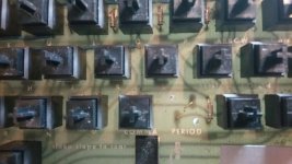
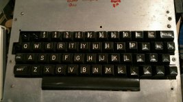
Okay so.. I think I understand (maybe) what's going on here. Here's my KBD-3:

20160429_162309_resized.jpg

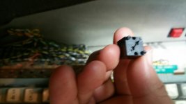
Looks nice, complete.. etc. Unfortunately the fall that brought this unit back to life caused one of the keyswitches to pop out. So when I pulled the keytops I have those two pieces of copper wire that form the 'bridge' I guess between contact points:

20160430_110254_resized.jpg

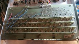
Here's the backside - note the 'encoder bars' I think SWTPC called them:

20160430_110233_resized.jpg

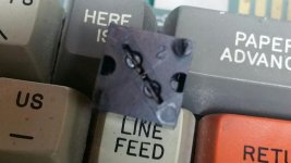
And then here is the bottom of the switch. Since the switches are soldered in as a unit, The wires I guess were somehow clipped into the bottom.

20160430_110402_resized.jpg 20160430_111857_resized.jpg

I'm still desperately looking for info on how the keyswitches themselves work, but if you look closely you can see a tiny copper wire running perpendicular to where the two contact wires would be. So I'm guessing pressing the switch down causes that wire to bridge the gap between the contact wires? Or maybe it's in reverse, pressing it breaks the bridge? No idea. What I do know is on only a few keys do I have maximum resistance when the key is unpressed. All of them register different levels of resistance. I'm guessing the middle wire must be stuck down on many of them. But the only way I could see to fix that is to desolder each key and then try to press the wire back up? And the plastic housing doesn't seem to have any simple way to come apart...
 
Okay so I found the schematic (I think) here: http://www.swtpc.com/mholley/PopularElectronics/Apr1974/PE_Apr1974.htm

If I understand correctly, Bit 1 = the pin marked 1, Bit 2 = pin marked 2 etc on the keyboard PCB where the connector goes out. When I power on, my logic probe always records the same bits set:

Bit 1 = 0
Bit 2 = 1
Bit 3 = 0
Bit 4 = 1
Bit 5 = 1
Bit 6 = 0
Bit 7 = 0

Or 0101100.

Here's their ASCII table: http://www.swtpc.com/mholley/PopularElectronics/Apr1974/PE_Apr_1974_pg31.jpg

Now, this is where I get confused. To help read the table, they give a couple of examples. They tell you the first four bits are from the left, the last three are from the top. They give H as an example: 100-1000. But I can only read it that way if I read it backwards -- from Bit 7 back to Bit 1 (top to bottom). So I'm confused. Based on their wording, the code my keyboard opens at is 'SUB'. But based on their H example, by code is actually a comma (,). So yeah, I don't quite get it. Did they goof in the wording? Comma would make more sense.

If comma is the case and nothing changes it, would I presume that key is stuck? Or the ICs? What'd be the best way to nail that down?
 
Just for curiosity I checked the comma key.. it appears to be functioning properly in terms of resistance, though no comma is produced when you press it with the machine on.
 
That schematic and article is exactly the same as the one I've got for the KBD2, right down to the RTL hex inverters.

But I thought you said something about CMOS...?

If this were mine, I'd first check the function of the inverters--these are very old technology--RTL was already obsolete by the time the PE article was published.
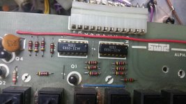

These are the ics I have:

1462133151907194731220.jpg

Don't know if they're the same thing as MC789P (I can't find the numbers up top anywhere online). I'm assuming RTL though. If you have any tips on how to check them I'd be most appreciative. My logic probe indicates the same legs on the lower one are always high. That's as much as I know there.. but I don't know if that's being driven by stuck keys or stuck IC.

The 'K' pin on the board according to that document is supposed to be high except when a key is pressed, however in the CT1024 manual it states it should be the opposite, and in my case, it is.. Low.

I would kind of think if the keys were bad hammering them would at least produce something.. brief changes in state on those chip legs or K line. But it's solid.
 
Yup, the look of the chips tell me that they're someone's Moto "house number" RTL chips. You can verify the function by simply applying power to the board, and seeing if the output of each inverter is the inverse of the input. Pressing a few keys should cause the various inputs to change state. My guess is that one or more of the inverter sections is bad. Diodes usually don't go bad--and that's good. But old plastic RTL hadn't gotten the encapsulation thing down 100% in 1972, which is what these are.
 
Yup, the look of the chips tell me that they're someone's Moto "house number" RTL chips. You can verify the function by simply applying power to the board, and seeing if the output of each inverter is the inverse of the input. Pressing a few keys should cause the various inputs to change state. My guess is that one or more of the inverter sections is bad. Diodes usually don't go bad--and that's good. But old plastic RTL hadn't gotten the encapsulation thing down 100% in 1972, which is what these are.

Yeah I'm not getting anything anywhere. They are locked in their present states.

I wonder if I already have replacements on hand. I have tons of TI and Fairchild hex inverters.. wonder how hard it'd be to find something compatible. Or if I should just order mc789s.
 
The good news is that a lot of these were made; the bad news is that RTL is 1960s logic and is expensive. I can find prices from $6-10 the each.

The MC889P is the commercial-ratings version.

It's kind of silly--the 789 hex inverter is basically 12 resistors and 6 transistors.
 
Back
Top