• Please review our updated Terms and Rules here

SWTPC TVT2 Under Repair

So I removed the original resistor and tested it. It comes out at 4.7k. I measured the two pads it soldered into at the bottom.. resistance is 5.2k now. I then installed the 'new' 4.7 resistor.. back to 2.5k?!
 
Oh, and here's another interesting factoid. Guess what's at the end of the trace R13 is on? The N key. The only key that sometimes works, and that on startup produces itself sometimes.
 
So I removed the original resistor and tested it. It comes out at 4.7k. I measured the two pads it soldered into at the bottom.. resistance is 5.2k now. I then installed the 'new' 4.7 resistor.. back to 2.5k?!

1/Rt = 1/R1+ 1/R2, right? So 1/ (1/4700+1/5200) = 2469 Close enough?

N is also on the same line as FV6> and up-arrow

Go back a page, and you'll see that you observed at powerup:
Bit 1 = 0
Bit 2 = 1
Bit 3 = 1
Bit 4 = 1
Bit 5 = 0
Bit 6 = 0
Bit 7 = 1

Which is "N". The problem is that bit 1 should be 1, so you'd be getting "O".
 
I pulled the N key out. Now R13 is 4.7 and now bits on startup are as follows:

Bit 1=1
Bit 2=1
Bit 3=1
Bit 4=1
Bit 5=0
Bit 6=1
Bit 7=0

Other interesting developments.

Bit 1 still does not change. Pin 14 on IC2 is low. When I hit a key, pin 14 goes from low to... nothing.. no lights on my probe. Pin 1 remains high.

Now on strobe, on pin 8 we see a state change from low to high pressing most keys. A few number keys don't produce any change. Pin 7 however does not change states, it remains solidly high. Not sure why that is. Before with the leg of pin 8 cut, all I had to do was bridge it with my probe and it would send out characters. With some solder to bridge the leg again, it's seeing changes on that side but not relaying them across.
 
Ah... ok.. on strobe, my solder job didn't properly rejoin the pin leg. When I bridge them manually and hold it.. strobe works.. hitting a key produces a character.. I don't have to short/unshort like I did before. Man.. getting close!!
 
Woohoo! Got it (sort of)! I fixed my solder job on pin 8 of IC2 and pin 14 on IC1. Now bit 1 is changing, and every key I hit that still works produces its proper key. Nice! But, it always produces a space after.

And of course, a number of keys don't work. Which is a bit of a problem because replacements are almost impossible to locate.
 
Correction. It's producing the space *before* the character. So if I type S, it does <space>S.
 
Checked the space bar's continuity.. my DMM can't get a read on it. It just keeps trying to figure it out endlessly (on mine little dots go back and forth while it calculates. On space, it never comes out of that).
 
Clearly, you've got a mechanical key issue now. The extra space is probably a bounce or a stuck key, hard to say.

Do you understand why some prefer analog (e.g. Simpson 260) VOMs? Sometimes, there's nothing like old-school metering.

Heck, I still own a VTVM.
 
I used my analog on the space bar and it kind of looks like it's shorted a bit. I guess I'll have to try removing it tomorrow. I wonder if I could find similar keyswitches that'll do the job and work with my keytops. Or if there's a way to rebuild these ones.
 
What does the underside of your keycaps look like? How tall is each keyswitch (without the key stem)?

These weren't the best keyswitches available, even at the time. You might try squirting some contact cleaner into the switch and working it a bit.
 
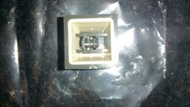
This is the bottom here.

20160430_111857_resized.jpg

I don't quite understand how it works.. you can see the plastic keystem base moving down when you press it but I don't see anything happening with contacts, etc.

The 'base' (minus the keystem) is about 1/2 inch tall, 1/2 inch wide.
 
Can you scrounge a small, say, 0.1 uF cap? Try placing it between the keypress strobe output and ground. I wonder if you've got some ringing in the line.

I wanted to see the underside of a keycap--they're all different and it would be nice if we could find something that your caps could actually fit on.
 
Okay.. it appears the 'space' situation was caused by the absence of the cursor control board. Well, actually the board was installed, but I'd neglected to connect the appropriate cable to it. So that's good as far as that goes.

The original serial board doesn't work at all... as soon as I install it, I lose the keyboard. It's got an AY-5-1013 on it, but by the looks of it, an early one. The chip is white ceramic rather than plastic, soldered directly. I do have another serial board from my other CT1024.. same chip, but socketed and plastic. And it has two extra ICs at the lt side, as well as a timing crystal my original one doesn't have. I guess we'll give it a try and see what happens.

I tried contact cleaner on the keys I removed but no dice thus far.. max resistance now but no change when key pressed.
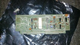
 
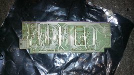
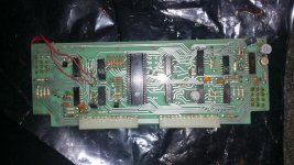
Here's the two serial boards. One that came with my first TVT (the one I'm working on now), the other came with the second.

First TVT:

20160507_092113.jpg 20160507_092136.jpg

Note the purple wire. I traced it to the user defined key just under the Enter key. No idea what it actually does.

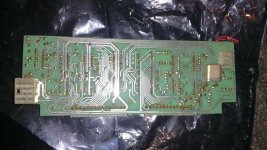
Now here's the board from the second (slightly newer) TVT:

20160507_092604.jpg 20160507_092612.jpg

They are jumpered a bit differently. The second TVT didn't have a screen read board so that appears to have been jumpered accordingly.

Obviously some pins are working.. it's definitely passing power through to the keyboard. I've tried turning echo on and off without effect.

Oh.. here's the back of the keycap.. sorry.. tired. :)

20160507_092627.jpg
 
It looks as if the keycap will fit a switch with a "cross" shaped actuator. Okay, that's something to go on.

The two serial boards are different in that the second includes the parts for the variable baud rate option. The first (which looks a lot like the one I did) has the baud rate fixed at 110, you'll see pads A and B jumpered. Why the long wires on the second board were necessary to jumper A and C is a mystery.

The purple wire on the second one that appears to go to the base of Q1 appears to be for generating a "BREAK" condition. (the TVT doesn't have such a facility normally).

So, get out your logic probe and start looking at the pins on the UART chip. For example, when you press a key, do you see a pulse train on pin 25? This is something that you can reason out, given the chip description in the serial board manual or even the UART datasheet.
 
Thanks Chuck. I'll get on it a bit later. Testing pin 25 will be tricky given how tight things are in there.. but I might just rig up my other CT1024 board outside the case to make it easier.

I did try at one point hooking up a serial terminal (I *think* the pinout for the connector that's on the back (DB25 female) conform to RS232) at 110baud and same bit and parity settings as my working unit, but it did not seem to produce anything the connected terminal typed.
 
Back
Top