• Please review our updated Terms and Rules here

Dead Commodore 8032 CBM

Juleshsmith

Experienced Member
Joined
May 1, 2012
Messages
53
Location
Melbourne, Victoria, Australia
Hi VCFED world.

My beloved CBM 8032 died last week As is often the case, I proudly showed her off to dinner guests last Saturday night, hit the power button... NOTHING!!!, not even the cheerful welcoming 'chirp'. I was guttered, as were my guests. She was last turned on and working approx 2 weeks ago. No signs of illness then. Hasn't been moved.

She was last sick in 2012 and the wonderful people on VCFED guided me through her recovery.

I was thinking this time I'd take it to a pro, but alas we don't really have anyone near where I live who repairs vintage computers.

I have an elementary knowledge of electronics, so need a lot of hand holding (as you would have noticed from my last post)

Here's what I know:
1) No chirp on start up, no video display, but there is a faint glow coming from the back of the CRT.

2) The PSU shows the following; Pins 9 and 11= 22.4VAC (S/B 21VAC), Pins 4 and 6 = 18.6VAC (S/B 22VAC), Pins 7 and 8 + 16.8VAC (S/B 18VAC)- Are these acceptable voltages?

3) Power is getting to the data cassette (runs when you hit play, fast fwd etc)

4) No obvious 'hot' chips. No obvious damage or dry joints although I only had a quick scan but could look more closely if I knew which chips to look at.

5) There are previous blogs I've read about dead 8032s, but a bit above my skill set... http://www.vcfed.org/forum/archive/i...p/t-40896.html

I have a second non working 8032 which I can use for parts

In simple terms, where do I start? I don't have a suitable meter to test caps but I could purchase one if that would be a good start?

Which chips are possibly the suspects? Could you also give me their location (E.G. UA9 etc)

Many many thx guys. And so the journey begins...
 
And so the journey begins...

OK, you will need a DVM or at least a good VOM. Make sure the battery in it is good. You first need to find out if the problem is in the main board or in the CRT section. It could be for example that a bad ROM or something is keeping the 6545 CRT Controller from being initialized and without a good Horizontal Drive signal, there will be no high voltage generated and therefore a dark screen.

First thing, Power off and press on all the socketed chips and jiggle/reseat the connectors including the J7 video connector to remove any oxide on the connections. Power up and see if any better. But before you remove any connectors/cables, take photos to make sure you can hook things back up correctly.

Then you should check if you have good DC voltages. With the black (-) probe attached to the PET chassis for a ground, Check a 4116 RAM chip like UA4 and verify the voltage on the following pins:
pin 1 -5V
pin 8 +12V
pin 9 +5V

Then look for an active Horizontal Drive on UC2- pin 3. It is a pulsing signal but should have a DC average reading of over 1.5 VDC. If it is zero there is probably a problem on the main board.

That should get you started. With a little good luck, you will get your beloved PET back on the air.
 
Excellent, thx dave_m!

Sound like a really good start. I have a VOM but a bottom of the range, and I don't think it's able to test caps. I've jiggled and reset the connectors but alas no change.

Couple of questions before I start... if the problem was in the CRT section, would you still expect to hear the "chirp" on start up (mine has no "chirp")? If that was the case then you could rule out that the problem was in the CRT section?

Thx :)
 
Couple of questions before I start... if the problem was in the CRT section, would you still expect to hear the "chirp" on start up (mine has no "chirp")? If that was the case then you could rule out that the problem was in the CRT section?

Yes, you are right. No chirp probably means the main board has the problem. There may be no pulsing on the Horizontal Drive signal as the 6545 may not be initialized. Check voltages then let us know what chips are on sockets for easy replacement. Can you solder if necessary?
 
PS- UC 2 pin 3 was a solid + 5v (not pulsating)

OK, good measurements. Power looks OK and no activity from the 6545 CRTC so most likely the computer is not running in program. Check the SYNC signal to see if the CPU is fetching instructions or is hung up. UB14-pin 7 on the 6502 chip. If it reads zero, there are no instruction fetches going on. It should read over 1 volt. Also check Phase 2 Output Clock on pin 39 of the 6502 (UB14). It should be running at 1 MHz square wave and so read about 2.5V on the DC Voltmeter. Can you borrow a scope if needed?
-Dave
 
6502 (UB14) pin 7 = +29.5v
Pin 39 = +2.3v

I've got a scope Dave but have never used it (time to learn!)

RE socketed chips. Most chips are hard wired. A few years ago I socketed a few of the RAM chips. 6502 is socketed.

Yep, I can solder! And as I mention, I have a DOA 8032 I can use for spares....

Really appreciate your step by step help on this :)
 
6502 (UB14) pin 7 = +29.5v
Pin 39 = +2.3v

I've got a scope Dave but have never used it (time to learn!)

If you meant that CPU pin 7 (Sync) is about 30 mV or a definite LOW, then the PET may have executed the dreaded KILL instruction. It is an illegal OP Code that causes the machine to wait forever. This may be because the CPU read from a bad ROM. Take a look at the most significant bits of the address bus (A15, A14, A13 and A12) to see if it might point to the bad ROM. For example A15 A14 A13 A12 = 1110 then the E000 address ROM may be bad (UD7). See sheet 4 of the schematic for ROM addresses. If a ROM is bad you will have options to proceed. You can attempt to unsolder and replace a 24 pin ROM or just replace all RAM and ROM at once with a small RAM/ROM replacement board that fits easily in the CPU socket. If you decide to replace the ROM, I will send you an EPROM replacement. Anyway, one step at a time.
 
Ah, yep 30 mV (didn't see the "m" on my new multimeter)

"Take a look at the most significant bits of the address bus (A15, A14, A13 and A12) to see if it might point to the bad ROM. For example A15 A14 A13 A12 = 1110 then the E000 address ROM may be bad (UD7)"


Ok, just getting a little lost now (pls forgive my ignorance)... What do you mean by "significant bits" ? When you say A15 is that UA15 (etc)? And not sure what you mean with "A15 A14... =1110" What's "1110"

I tested all the RAMs (pins 1, 8, 9) and the only one that was off was UA20 Pin 9 = 16mV

Thx again Dave
 
Ok, just getting a little lost now (pls forgive my ignorance)... What do you mean by "significant bits" ? When you say A15 is that UA15 (etc)? And not sure what you mean with "A15 A14... =1110" What's "1110"

I tested all the RAMs (pins 1, 8, 9) and the only one that was off was UA20 Pin 9 = 16mV

UA20 is not a RAM chip so that is OK. I'll explain address lines with follow up message. In mean time look at sheet one of schematic and find the 16 address lines. These signals are named BA15 through BA0 (for buffered Address). This address 'bus' of 16 signals is routed to many chips including the RAM, ROM and Input/Output chips like the 6520 and 6522.
-Dave
 
There are 16 address lines out of the 6502 CPU. This is how the CPU identifies which particular memory or I/O location it wants to either read from or write to. Since each address line can either be in a 1 state(+5V) or 0 state (0 V), there are a total of two to the power of 16 combinations of addresses which equals over 64,000 locations (64K).

Anyway, the state of the upper four address lines (BA15, BA14, BA13 and BA12) can give us a clue as to which of the five ROMs the CPU is trying to 'read'. So check the voltage of each signal starting with BA15 and write down the pattern, i.e., +5C, +5V, 0V and +5V. This tells us what ROM was being addressed. This example pattern means the upper bits were in a 1101 state which in computer shorthand is called hexadecimal 'D'. This means the UD8 ROM is being addressed and may be bad as the computer is hung up there. Measure those 4 signals and report back.
-Dave
 
Excellent Dave.

Not sure what this means...

AB15 +62mV
AB14 +52mV
AB13 +51mV
AB12 + 41mV

I'll have to think about this. Apparently the machine got stuck while doing something in low RAM. It should not have been fetching instructions there. It should have been reading or writing data into perhaps zero page locations which should not have hung it up, but bad data in zero page RAM could have certainly caused the machine not to boot. So it is possible that you have bad RAM. Time for a piggyback test on the lower 16K RAM. Do you happen to have any spare 4116 dynamic RAM chips?
 
Ok. I've piggy-backed all the lower 16k RAMs (4116s) (UA5, UA7... UA9) but alas no change.

Most of the DOA 8032 chips are socketed which makes it's easy. About 20% of the good 8032s are socketed.

Any other recommendations Dave?
 
Fluctuating... does that still go along with your bad RAM theory Dave?

Not really, as now the addresses seem to fluctuate between $Exxx and $Axxx. 'E' is OK as that is the EDIT ROM where the screen is handled, but what does not make sense is how the machine gets to $Axxx. That is the spare ROM location. You may need to look with the scope to tell how much pulsing is going on. If we get lucky and the Edit ROM is bad, no soldering is necessary as that part is always on a socket. Make sure UD7 (EDIT ROM) is properly seated in socket. How tarnished does the UD7 socket look? Commodore used cheap sockets.
-Dave
 
Reseated UD7 Dave. Socket looks good. No dry joints underneath Alas no change :-(

At this stage, you have some options.

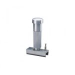
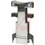
If your 8032 happens to have the two PIA and VIA chips on sockets (normally they are soldered), you could remove them and if one of them is the only problem, the welcome screen will come up. Also replace the 6502 CPU, but that chip rarely fails. Use proper 24/40 pin chip removal and insertion tools to avoid bending pins. See photos.

If you feel like a lot of troubleshooting, build a simple NO OP Generator, then you can fire up your scope, and start checking address lines and chip selects hoping to spot a problem.

If you want a quick chance to fix everything without troubleshooting, you can buy a RAM/ROM replacement module as there is a good likelihood that it's one of those chips. At least two good vendors sell a small board that fits into the CPU socket. The cost is about $70 USD maybe a little more with shipping so far away.

I could send you some replacement EPROMs if you want to try unsoldering 24 pin chips. I've always been terrified when I have to remove a big chip as there is a possibility of damaging traces and plated thru holes. But using good technique which we can show you, it is doable.

One question: What technique did you use with the piggyback test. With power off, did you place one RAM at a time and then try a power-on to see any flicker of change on the screen?


40J743_AS01.jpg 70176423_large.jpg
 
Back
Top