• Please review our updated Terms and Rules here

Dead Commodore 8032 CBM

I have write petest in 2532 eprom and i've inserted in UD6 but when i power on computer,screen are always black :(

In normal conditions,when i turn on,i can hear 3 beep sounds..but screen are totaly black..
In pin 23 of 6545 i see clock signal only...but in 38 nothing.

You should also see a clock on pin 21 (CLK1) and pulsing on pin 24 (A0). Also, see if you find pulsing on the data lines (pin 26 to pin 33 of the 6545). Look for signals that look strange like either constant low or maybe going to levels other than +5 or 0. If two signals are shorted together, the signal will look odd.

If all is OK, then the 6545 may be bad. I say this because the beep implies the CPU is executing proper instructions on power-up, and the Sync signal indicates the CPU is fetching instructions.

With pettest2, you are not depending on other ROMs or RAM to work and also as you have replaced the ROMs and lower 16K RAM (you did replace the ODD RAM chips from UA5 to UA 19 and not the even?).

Other things to try before replacing the 6545 CRT Controller:

If the two 6520s (PIA) and the 6522 (VIA) are on sockets, you can try removing them to see if you get some screen activity. Sometimes a failure there can cause a dark screen.

Make a simple NOP generator (using a 40 pin socket) and check that the address lines all increment correctly.

Hello,i've checked clock on pin 21 and pulsing on 24 and seems ok!
i've desoldered pia and via but nothing to do...
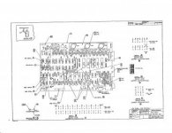
I've see that pin 3 in UC3 are not cutted...in schematic i read that UC3 PIN3 is cutted off.....
8032080-7.jpg

It's ok?

I've buy a new 6545...when he arrives to me,i'll try to change!
 
Hello,i've checked clock on pin 21 and pulsing on 24 and seems ok!
i've desoldered pia and via but nothing to do...
I've see that pin 3 in UC3 are not cutted...in schematic i read that UC3 PIN3 is cutted off.....

I did not want you to unsolder the PIA and VIA. If you were going to unsolder big chips, you should have started with the 6545 CRT Controller. Anyway it appears you must be good at replacing big chips.

on the latest 8032 schematic, pin 3 of UC3 (decoder) is shown tied to +5V. On the older Universal boards, it is tied to Phase 2 clock. In theory both should work, but having the signal tied to +5V, will make the circuit faster. In your case the signal is left floating which might make the circuit noisy. Later you may consider tying the input to +5V.


Hello Dave,
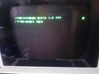
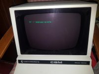
i have changed 6545 and finally,for the first time,i've seen the light ;)
Unfortunately there are some problems... :(
Can you help me with this screen please?
Thanks again!
20180108_173624.jpg
 
OK, looking much better! Your monitor is fine.

Maybe bad video RAM or associated circuitry. Please provide a close up the screen. Is there a one second blinking cursor on the left edge?
 
Hi guys,hello Dave,
i've replaced the 2 video ram with vic20 rams but it's the same...
In this Pet i have used tms2532 eprom and mbm2716....are correct?
I can not find a definitive solution for this poor pet :(
schermo.jpg
 
Hi guys,hello Dave,
i've replaced the 2 video ram with vic20 rams but it's the same...

The screen output looks very improved compared to the last photo you posted. Why do you say it is the same?

Again: is there a blinking cursor? This will indicate a working interrupt routine.

The Texas Instruments EPROM is fine to use and any 2716 is OK for the Editor ROM.

The PET is close to working.
-Dave
 
A faulty character generator ROM?

It seems that specific letters have been replaced by blocks (the 'R' in COMMODORE and FREE, the 'B' in BASIC and BYTES). Also, some of the other characters may have a bit of 'bit rot' possibly?

Just an observation...

Dave
 
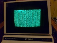
The screen is never the same ...
Each time i switch on, the screen often changes ...
The cursor is not flashing ...
I checked all the roms and they seem to be ok, compare with those of zimmer.
This is the screen that appears now ...
errore.jpg
 
A faulty character generator ROM?

It seems that specific letters have been replaced by blocks (the 'R' in COMMODORE and FREE, the 'B' in BASIC and BYTES). Also, some of the other characters may have a bit of 'bit rot' possibly?

Just an observation...

Dave

I noticed that too, but the inverse video is controlled by bit 7 in the video RAM, and that signal does not connect to the character generator. A very interesting problem.
 
I have write petest in 2532 eprom and i've inserted in UD6 but when i power on computer,screen are always black :(

Sorry, I missed this message. For some reason I do not get alerts with your posts.

With pettest2, you must let it run for up to 20 seconds before you will see a screen display. This is because the 6545 CRTC initialization routine was put at the end of the RAM test, and the program must run test once before CRTC initialization.

The silly reason for this time delay was that I did not have a 6502 Assembler handy, and it was easiest for me to hand-code the machine language routine to the end of the guy's pettest program just before it looped back to the beginning of the test. I should fix this problem.


Pettester in Ud6 unfortunately,it shows nothing even after 5 minutes....
Now i order new eprom hitachi and i'll try to rewrite this!
Thanks
 
Pettester in Ud6 unfortunately,it shows nothing even after 5 minutes....
Now i order new eprom hitachi and i'll try to rewrite this!
Thanks

So you are saying that after fixing the 6545 CRTC, 'pettest2' shows a dark screen? That is hard to understand as the program is simple and does not use interrupts, stack etc.

To see a disassembly of the code get this file: pettest2.txt.
Do not forget to add the RESET Vector into PROM address $0FFC of $00 and $0FFD of $F0 for the proper starting address ($F000).

Hang in there. you are getting close to fixing the PET.
-Dave
 
>>> I noticed that too, but the inverse video is controlled by bit 7 in the video RAM, and that signal does not connect to the character generator. A very interesting problem.

I was more thinking that the 'bits' forming the character had all been set to a '1' rather than anything to do with the inverse video signal.

A long shot I know - but I fixed a very expensive problem at work over Christmas with a long shot idea - so I am on a roll!

Dave
 
With a changing pattern on each reset, it could be a problem of no refresh. Is it better or worse if
it powers up cold?
Dwight
 
I was more thinking that the 'bits' forming the character had all been set to a '1' rather than anything to do with the inverse video signal.

Dave

Hi Dave,
I see you you are saying: corrupt data locations in the Character ROM. Quite possible, but eight consecutive scan line outputs would have to be corrupt to get an inverse space character. But it may explain that crazy looking screen in the first photo in message #44.
 
Last edited:
Back
Top