- VCF South West - June 14 - 16, Davidson-Gundy Alumni Center at University of Texas at Dallas
- VCF West - Aug 2 - 3, Computer History Museum, Mountain View, CA
- VCF Midwest - Sept 7 - 8 2024, Schaumburg, IL
- VCF SoCal - Mid February 2025, Location TBD, Southern CA
- VCF East - April 2025, Infoage Museum, Wall NJ
-
Please review our updated Terms and Rules here
- Forums
- Companies
- IBM Computers, PCs, Clones and Descendants
- PCs and Clones (XT and early AT class machines)
You are using an out of date browser. It may not display this or other websites correctly.
You should upgrade or use an alternative browser.
You should upgrade or use an alternative browser.
Book 8088 discovery and modification thread
- Thread starter Retroplayer
- Start date
thanks a lot! I've been lurking for a while. First computer was Tandy 1000SX with 640KB and dual 360K 5.25" without HDD. Recently bought a couple of Book8088 V2 systems to mess around with, and so my kids / future engineers can learn the joys of preparing and tuning config.sys & autoexec.bat. Now I have UMB ISA cards, EEPROMS, various 8088 and 8087 variants, serial devices, and other stuff in transit. I'm a longtime enthusiast, working my dream job in the industry now. Awesome to be here - so much great info and really really smart folks! take care and thanks again!
n0p
Experienced Member
No, no LED.. and actually.. I just tried something.. and apparently it's the opposite. (so it's n0p's fault.. lol and now i can't delete my post)
@n0p If I put my jumper on, i can switch between 4.77 and 8... but with the jumper off, it's ONLY 4.77... (according to syscheck).. so it appears we were slightly wrong..... gah. Did you test or was this all just from the schematic?
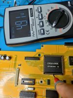
I'm absolutely sure that line is pulled high when turbo is off at least on V1, and i doubt that part changed in V2 (reattached photo from test). But we can fix that anyway, by putting +5V with resistor to "input" part.
Ah thanks.
@n0p could you perhaps write a simple program that just emulates pressing the key combination to activate turbo (if turbo is not already on) to put in autoexec.bat (or config.sys I don't know)
The problem is Turbo is microcontroller controlled, it sets the line and led state, it's just impossible on software level.
Attachments
n0p
Experienced Member
As i have a spare board now, i've quick tested that at least for sanity check.
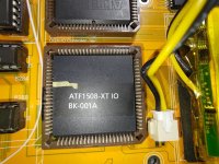
Pin 14 from STM now goes to pin 2 on CLPD.
It still has 5V on it on start (see photo).
I can suggest that in V2 you need to pull pin 2 down as it seems on V2 it treats floating state on that pin as "turbo off".
Quick test would be - jumper off, 20K resistor to ground from pin 2.
Pin 14 from STM now goes to pin 2 on CLPD.
It still has 5V on it on start (see photo).
I can suggest that in V2 you need to pull pin 2 down as it seems on V2 it treats floating state on that pin as "turbo off".
Quick test would be - jumper off, 20K resistor to ground from pin 2.
Attachments
I'll have to crack it back open, find a 20k resistor (you think it needs ot be that high?) and at least i can still use the wiring, jsut move it (if this works)As i have a spare board now, i've quick tested that at least for sanity check.
Pin 14 from STM now goes to pin 2 on CLPD.
It still has 5V on it on start (see photo).
I can suggest that in V2 you need to pull pin 2 down as it seems on V2 it treats floating state on that pin as "turbo off".
Quick test would be - jumper off, 20K resistor to ground from pin 2.
n0p
Experienced Member
I'll have to crack it back open, find a 20k resistor (you think it needs ot be that high?) and at least i can still use the wiring, jsut move it (if this works)
I'm unsure of exact needed value, just to be on the safe side. Here Sergey suggests 10K is good enough: https://forum.vcfed.org/index.php?t...ards-working-9600.1244414/page-2#post-1334871
Too strong of a pullup/down can make it hard to overcome and too weak.. yeah.., and I'm more likely to find a 10k than a 20k... no local electronic stores around here anymore.I'm unsure of exact needed value, just to be on the safe side. Here Sergey suggests 10K is good enough: https://forum.vcfed.org/index.php?t...ards-working-9600.1244414/page-2#post-1334871
n0p
Experienced Member
OK. while we working on good solution for hardware turbo button for V2 ") i've decided to do one thing, iirc @Yrouel tried some time ago - flashing LCD board EEPROM chip directly on board, as i found some 800x480 firmwares and wanted to test them with some efficient way.
i've decided to do one thing, iirc @Yrouel tried some time ago - flashing LCD board EEPROM chip directly on board, as i found some 800x480 firmwares and wanted to test them with some efficient way.
First try - i connected SOIC clip to my spare LCD board.

It doesn't sit very good though. Anyway, i could read fw, but programmer complained about wrong ID. Flashed new one, it stated that programming failed, though back reading showed it was ok actually.
I connected flashed board to my V2 display and fw didn't work (not that i expected a miracle).
This time i decided to flash chip right there, and to my my surprise it didn't complain about ID and flashed good VGA firmware w/o error as well (some capacitors have charged?)
So far it seems to be fastest way to update firmware on LCD board.
(I unscrewed the board so i could sit SOIC clip better and wires itself won't pull it off, but it's not necessary)


--
For future reference - i've tried Flash-546 and Flash-583b from now dead OpenRTD project, and they didn't work. Maybe, just maybe they expect some power button to be pressed
i've decided to do one thing, iirc @Yrouel tried some time ago - flashing LCD board EEPROM chip directly on board, as i found some 800x480 firmwares and wanted to test them with some efficient way.First try - i connected SOIC clip to my spare LCD board.
It doesn't sit very good though. Anyway, i could read fw, but programmer complained about wrong ID. Flashed new one, it stated that programming failed, though back reading showed it was ok actually.
I connected flashed board to my V2 display and fw didn't work (not that i expected a miracle
).This time i decided to flash chip right there, and to my my surprise it didn't complain about ID and flashed good VGA firmware w/o error as well (some capacitors have charged?)
So far it seems to be fastest way to update firmware on LCD board.
(I unscrewed the board so i could sit SOIC clip better and wires itself won't pull it off, but it's not necessary)
--
For future reference - i've tried Flash-546 and Flash-583b from now dead OpenRTD project, and they didn't work. Maybe, just maybe they expect some power button to be pressed
Last edited:
Dear n0p, I have a book 8088 v2 with ISA expansion board, and I want to have the opportunity to connect it to external VGA flat panel display. I am from Kyiv as well. I tried to do it in the following ways: connected an external ISA VGA card, but unfortunately it was 16bit, I hoped it would operate in 8bit mode, but no. If I understand correctly it is possible to built in VGA out connector. Unfortunately, I am not very good in soldering, as I am not that young. I am willing either to buy an external 8bit VGA card which would be compatible, or built in an VGA connector, I will pay for everythingYou're welcome!
For VGA issues you can ask seller for replacement LCD board - they would send it w/o any problems. Simplest way to check LCD fw - set mode 12h (via checkit or https://github.com/jinshin/Book8088/blob/main/MODE12H.COM). Blank screen - you have CGA firmware.
To some point, external screen mod for VGA would be easy, as it already has VGA connector, just in different form and doesn't require any convertors. But it won't look nice.
You'll need to make a connector, for board it's 12P 1.25mm https://www.aliexpress.com/item/1005006003135511.html and solder a VGA DE-15 to it.
Board connector pinout attached
.<phone number removed>. Thank You!
Last edited by a moderator:
Yrouel
Member
iirc @Yrouel tried some time ago - flashing LCD board EEPROM chip directly on board, as i found some 800x480 firmwares and wanted to test them with some efficient way.
Yeah with my TL866CS I usually have issues trying to program these kind of EEPROMs while mounted, it always complains about high current so I end up having to desolder them.
Looking forward to read more about the new firmwares you're testing. Also have you seen the user on Vogons that managed to program it through DDC?
n0p
Experienced Member
Yeah with my TL866CS I usually have issues trying to program these kind of EEPROMs while mounted, it always complains about high current so I end up having to desolder them.
Looking forward to read more about the new firmwares you're testing. Also have you seen the user on Vogons that managed to program it through DDC?
So far no luck, but it's just a hit and miss game. I've also run a search through https://github.com/riftlab/RTD2660_PCB800099 and didn't find a firmware used in the Book VGA LCD
I don't think that VGA firmware was made specifically for Book and trying to find the source of it to at least understand the base they used - as there two VGA firmwares (i received my board with quite bad one, and it was showing "No support" with hieroglyphs on CGA)Story for CGA is maybe more interesting, as pengan mentioned that Shan "hacked" the firmware to support 15Khz. Why he didn't hack current VGA fw for it?
OpenRTD project references i've found states that it supports 15Khz as well, but both firmwares i found just give the black screen when flashed on Book LCD board.
One for "800x480 AT070TN90" (that mark was on @sorphin LCD) showed white screen with some horizontal lines and then off.
--
Yes, i've seen https://www.vogons.org/viewtopic.php?p=1227721#p1227721. Really cool solution, but i personally fail at prerequisites :D Only PC with VGA i have is my immortal P200MMX and wouldn't use it for that.
As i side note i've looked at those 4 pins a lot myself (they located at back of rev1.2 board) and traced middle two to SCL / SDA lines on RTD chip iirc. So some serial programmer with soic clip should probably do, but i never got to testing. If that matters - at first i was using borrowed T48 (never thought i will get so deep into that
), but some time ago i bought myself one with basic adapter set for about $50. Pretty cheap for the fun it offers But those blue leds...--
A bit more. Microprocessor inside RTD2660 appears to be Intel 8051. Reko https://github.com/uxmal/reko/releases (to my surprise) evolved to quite good state since last time i checked and decompiles RTD firmware quite nice. Other thing is what we should look for? :D Would be nice to have hacked and unhacked fw to compare and have some starting point.
Last edited:
Wonder if it'll work under Wine... (Otherwise it's a Windows VM or thin client for it)A bit more. Microprocessor inside RTD2660 appears to be Intel 8051. Reko https://github.com/uxmal/reko/releases (to my surprise) evolved to quite good state since last time i checked and decompiles RTD firmware quite nice. Other thing is what we should look for? :D Would be nice to have hacked and unhacked fw to compare and have some starting point.
n0p
Experienced Member
Dear n0p, I have a book 8088 v2 with ISA expansion board, and I want to have the opportunity to connect it to external VGA flat panel display. I am from Kyiv as well. I tried to do it in the following ways: connected an external ISA VGA card, but unfortunately it was 16bit, I hoped it would operate in 8bit mode, but no. If I understand correctly it is possible to built in VGA out connector. Unfortunately, I am not very good in soldering, as I am not that young. I am willing either to buy an external 8bit VGA card which would be compatible, or built in an VGA connector, I will pay for everything
I just need to get a DE-15 connector for that. No promises thought
Вітаю!
Я тоже не молод и паять толком научился наверное год как
Но не проблема, у меня просто нет коннекторов и поиск займет некоторое время.
Не обещаю, но скорее всего через неделю-две сделаю пару коннекторов для VGA.
Смотрите, там один момент - нужно будет отключить дисплей со стороны материнской платы. Вам это будет норм?
Thank You! And if the display is disconnected from the side of the motherboard, will the internal notebook display be operational after that? As I plan to use the book not only as the stationary one with the external monitor, but as standalone computer as well. If need be there is no problem for me to buy all the necessary connectors and spares, just please provide a link to the store.I just need to get a DE-15 connector for that. No promises thought
Вітаю!
Я тоже не молод и паять толком научился наверное год как
Но не проблема, у меня просто нет коннекторов и поиск займет некоторое время.
Не обещаю, но скорее всего через неделю-две сделаю пару коннекторов для VGA.
Смотрите, там один момент - нужно будет отключить дисплей со стороны материнской платы. Вам это будет норм?
Вітаю! А смогу я после этого пользоваться ноутбуком если я потом отключу внешний дисплей? Вы скажите, если необходимо, я могу купить необходимые разъемы, только дайте ссылку на них.
n0p
Experienced Member
Thank You! And if the display is disconnected from the side of the motherboard, will the internal notebook display be operational after that? As I plan to use the book not only as the stationary one with the external monitor, but as standalone computer as well. If need be there is no problem for me to buy all the necessary connectors and spares, just please provide a link to the store.
Вітаю! А смогу я после этого пользоваться ноутбуком если я потом отключу внешний дисплей? Вы скажите, если необходимо, я могу купить необходимые разъемы, только дайте ссылку на них.
Straight answer requres testing on my side. So far idea is to disconnect internal display and connect cable for external. I do understand that might be quite a problem switching those. But i've no idea will connecting parallel cable work normally, as there might be voltage drop. CGA has TTL signals, VGA is another story. VGA connectors are not a problem, but i coudn't find 12P 1.25 connectors in Ukraine, and waiting for a month from Ali might be too much. I have a couple for testing, and migh tget to it next week.
Тут как. Пока идея в том, чтобы подлючить внешний дисплей вместо внутреннего. Это технически некрасиво, нужно выкручивать 9 шурупов каждый раз и т.д. Но я очень не уверен, будет ли работать подключение в параллель, т.к. напряжение на выходе может упасть. Надо проверять. Кабели JST 1.25 на 12 пин в Украине не купить, вообще нет. Но у меня есть пара штук, на тесты хватит.
В любом случае VGA коннектор будет некрасиво торчать из корпуса в районе портов.
С Буком V1 именно впилить разьем было не проблема, там прям на плате было запланировано гнездо, проблема была найти и купить RGB2HDMI конвертор.
Как бы то ни было, отпишу, когда/если что-то получится.
В любом случае VGA коннектор будет некрасиво торчать из корпуса в районе портов.
С Буком V1 именно впилить разьем было не проблема, там прям на плате было запланировано гнездо, проблема была найти и купить RGB2HDMI конвертор.
Как бы то ни было, отпишу, когда/если что-то получится.
Thank You! I believe many forum members would like to know the results of your tests!Straight answer requres testing on my side. So far idea is to disconnect internal display and connect cable for external. I do understand that might be quite a problem switching those. But i've no idea will connecting parallel cable work normally, as there might be voltage drop. CGA has TTL signals, VGA is another story. VGA connectors are not a problem, but i coudn't find 12P 1.25 connectors in Ukraine, and waiting for a month from Ali might be too much. I have a couple for testing, and migh tget to it next week.
Тут как. Пока идея в том, чтобы подлючить внешний дисплей вместо внутреннего. Это технически некрасиво, нужно выкручивать 9 шурупов каждый раз и т.д. Но я очень не уверен, будет ли работать подключение в параллель, т.к. напряжение на выходе может упасть. Надо проверять. Кабели JST 1.25 на 12 пин в Украине не купить, вообще нет. Но у меня есть пара штук, на тесты хватит.
В любом случае VGA коннектор будет некрасиво торчать из корпуса в районе портов.
С Буком V1 именно впилить разьем было не проблема, там прям на плате было запланировано гнездо, проблема была найти и купить RGB2HDMI конвертор.
Как бы то ни было, отпишу, когда/если что-то получится.
Hi there,
In the subject of Book8088, I published my USB Driver on GitHub.
No source by now, as I am not sure I am authorized to do so.

 github.com
In the subject of Book8088, I published my USB Driver on GitHub.
No source by now, as I am not sure I am authorized to do so.
GitHub - FreddyVRetro/CH375-USB-DRIVER: CH375 USB Driver for PC Modified for Speed (XT/286)
CH375 USB Driver for PC Modified for Speed (XT/286) - FreddyVRetro/CH375-USB-DRIVER
github.com
n0p
Experienced Member
Good news everyone!
I've made and tested VGA connector for VGA Book V2 (It might even work for CGA, more below)
So - i've got DE-15 connectors and to simplify testing decided to make a pass-through cable with a DE-15 branch (dunno how it that correctly called).
Needed parts: JST 1.25 12 pin cable, male connector for it, DE-15 female, optionally case for it, 9 wire ribbon.
Male connector part and cable itlsef:


Worth noting that pins on the male connector supposed to be held by board and not used this way - they may fall out when connecting cable to it, so hot glue is there to help a bit. Red, black and yellow cables supply 5V to LCD board, be careful on that part, we don't need that on VGA connector.
First test, i used simpler path - removed cover from display, that's -5 screws for job Internal LCD board disconnected.


 View attachment xenon2.mp4
Picture is somewhat dim, but quite good anyway. Did a shortest Xenon 2 run ever
Next, with internal LCD connected. I wouldn't say there's any difference on external display. But internal didn't work at all, just sometimes helplessly blinks (But that might be good actually)


Since i was there anyway, i connected my Book V1 via my new connector. Odd enough, it's somehow worked (it appears my display somewhat supports 15Khz), so if you got such VGA display, that may work for you with CGA.

Now, suggested cable position w/o making any changes to Book:

I've made and tested VGA connector for VGA Book V2 (It might even work for CGA, more below)
So - i've got DE-15 connectors and to simplify testing decided to make a pass-through cable with a DE-15 branch (dunno how it that correctly called).
Needed parts: JST 1.25 12 pin cable, male connector for it, DE-15 female, optionally case for it, 9 wire ribbon.
Male connector part and cable itlsef:
Worth noting that pins on the male connector supposed to be held by board and not used this way - they may fall out when connecting cable to it, so hot glue is there to help a bit. Red, black and yellow cables supply 5V to LCD board, be careful on that part, we don't need that on VGA connector.
First test, i used simpler path - removed cover from display, that's -5 screws for job
Internal LCD board disconnected.View attachment xenon2.mp4Picture is somewhat dim, but quite good anyway. Did a shortest Xenon 2 run ever
Next, with internal LCD connected. I wouldn't say there's any difference on external display. But internal didn't work at all, just sometimes helplessly blinks (But that might be good actually)
Since i was there anyway, i connected my Book V1 via my new connector. Odd enough, it's somehow worked (it appears my display somewhat supports 15Khz), so if you got such VGA display, that may work for you with CGA.
Now, suggested cable position w/o making any changes to Book:
n0p
Experienced Member
Putting VGA connector inside will require some drilling and shaving a bit off connector, or it won't fit.


I'm now thinking, if i will want to mod my BookV2, i'd probably use IDC-10 connector, but that will require drilling board and cutting conductive part i not have the heart to do atm.
I'm now thinking, if i will want to mod my BookV2, i'd probably use IDC-10 connector, but that will require drilling board and cutting conductive part i not have the heart to do atm.