jonathanjo
Member
- Joined
- Feb 18, 2024
- Messages
- 38
Hi Friends ... feel free to tell me it doesn't matter! I'm just starting to learn about QBUS and want to make sure to avoid casualties on my old equipment. Thanks!
For context I'm working on the power-good signals BDCOK etc for an H9275A backplane for a QBUS KDJ11J-D/S (main story over here).
Voltage?
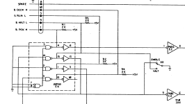
I'm confused by Diane showing a 120R resistor on her TTL debounce circuit, and saying:
My understanding is that QBUS is TTL, 5VDC, and that signals such as BDCOK are designed simply to be pulled low by an open-collector output:
Supermicrosystems Handbook says (p A-35):
Drive?
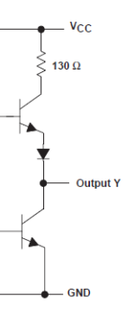
Everybody seems to drive this with ordinary TTL chips such as 74LS04, not open collector ones: I'd have expected 74LS05 for example.
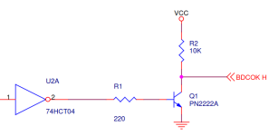
Except Frain which has what seems to be a good NPN drive but with an unnecessary pullup:

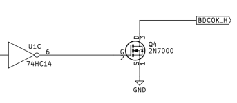
And Joe Lang who has the only one which looked right, an open-drain 2n7000.

For context I'm working on the power-good signals BDCOK etc for an H9275A backplane for a QBUS KDJ11J-D/S (main story over here).
Voltage?
I'm confused by Diane showing a 120R resistor on her TTL debounce circuit, and saying:
The resulting output has to be converted from TTL +5V logic to DEC Qbus +3.4V logic
My understanding is that QBUS is TTL, 5VDC, and that signals such as BDCOK are designed simply to be pulled low by an open-collector output:
Supermicrosystems Handbook says (p A-35):
- TTL Inputs Low/High=0.8V max/2.0V min, Outputs 0.4V max/2.4V min
- Devices driving the 120-Ohm bus must have open collector outputs and meet the following [sink/source specification].
Drive?
Everybody seems to drive this with ordinary TTL chips such as 74LS04, not open collector ones: I'd have expected 74LS05 for example.
Except Frain which has what seems to be a good NPN drive but with an unnecessary pullup:

And Joe Lang who has the only one which looked right, an open-drain 2n7000.

Last edited:


